
 Surface


Zhang

 NextPCB Capabilities
Printed Circuit Boards
NextPCB Capabilities
Printed Circuit Boards
 PCB Assembly
 Layer Buildup
 SMD-Stencils
 PCB Design-Aid & Layout
 Mechanics
 Quality
 Drills & Throughplating
 Factory & Certificate
 PCB Assembly Factory Show
Certificate
PCB Assembly Factory Show
Certificate
Support Team
Feedback:
support@nextpcb.com


NextPCB Vocabulary
Definition: Flexible PCB Assembly/FPC Assembly is the process of mounting electronic components onto a flexible substrate, such as polyimide (PI), PEEK, or transparent conductive polyester films. Unlike traditional rigid FR-4 boards, flexible circuits can bend, fold, or wrap, enabling compact, lightweight designs in tight or irregular spaces.
Simply put: It is the process of soldering components onto bendable circuit boards—like slapping chips onto a plastic sheet that twists without breaking.
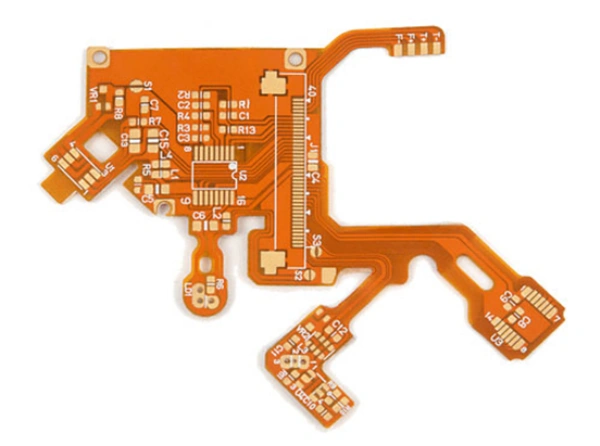
Flexible PCBs (FPCs) differ fundamentally from rigid PCBs in their “flexibility”. To assemble them effectively, manufacturers transform the FPC into a pseudo-rigid form, typically by mounting it onto a carrier or pallet.
Download the Full Flexible PCB Assembly Guide
- Mount carrier onto locating jig
- Insert the FPC onto carrier
- Overlay with a top plate or clamp for alignment
- Once fixed, lift the entire setup from the jig to proceed with solder paste printing, component placement, and reflow steps.
Optimize carrier choice based on production volume and FPC characteristics:
Incorporate high-temperature magnets and clamps to hold the FPC securely.
Offer adhesion and easy release.
Simple and affordable option.
Recommend Reading: The most comprehensive introduction to FPC PCB design principles
Ideal carrier materials include aluminum, synthetic stone (engineering plastics), or silicone—chosen for lightweight, rapid heat dissipation, and minimal thermal deformation.
| FPC Key Features | Details |
| Flexible Substrate | Polyimide for high heat resistance and flexibility; can bend, fold, or twist without damaging traces. |
| Component Mounting Process | Uses SMT or THT like rigid boards; requires careful handling to avoid tearing or creasing. |
| Lightweight & Space-Saving | Eliminates bulky wiring harnesses; enables compact device designs. |
| Thermal & Mechanical Considerations | Engineers fine-tune soldering profiles to prevent warping; use fixtures or stiffeners for stability. |
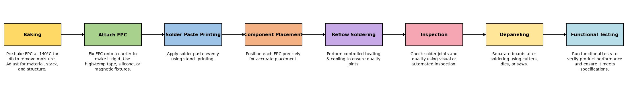
FPCs tend to absorb moisture during storage or shipping. To prevent soldering defects like delamination or bubbling, manufacturers perform low-temperature baking (typically 80–125 °C for 4–8 hours, depending on board thickness). They conduct sampling to optimize bake time, and stack only ~10–20 panels for uniform drying.
Flexible PCB assembly is widely used in consumer electronics, medical devices, IoT wearables, and automotive systems where miniaturization and movement tolerance are essential. Methods like tape-automated bonding (TAB) enable efficient chip-on-flex (COF) integration, offering high-speed, automated assembly for applications like mobile cameras and smart card modules.
More:
Learn PCB Assembly Services at NextPCB
Get a PCBA Quote Now!

Still, need help? Contact Us: support@nextpcb.com
Need a PCB or PCBA quote? Quote now

