
 Surface


Where do these technologies live? High-Speed powers computational logic, while High-Frequency powers wireless communication and sensing.

 NextPCB Capabilities
Printed Circuit Boards
NextPCB Capabilities
Printed Circuit Boards
 PCB Assembly
 Layer Buildup
 SMD-Stencils
 PCB Design-Aid & Layout
 Mechanics
 Quality
 Drills & Throughplating
 Factory & Certificate
 PCB Assembly Factory Show
Certificate
PCB Assembly Factory Show
Certificate
Support Team
Feedback:
support@nextpcb.com


Introduction
In the world of PCB design, the terms "High-Speed PCB" and "High-Frequency PCB" are often tossed around interchangeably. While there is a significant overlap—after all, high-frequency signals often travel at high speeds—from a design and manufacturing perspective, they are two distinct beasts.
Understanding the difference isn't just a matter of semantics; it dictates your choice of materials, your stack-up strategy, and your budget. Getting it wrong can lead to signal degradation, emission failures, or unnecessarily expensive manufacturing costs.
Are you building a superhighway for data, or a precision radio transmitter? Let’s break down the differences with a simple checklist and a deep dive into the core distinctions.
Before we get to the checklist, we need to define the "mission" of your circuit.
Not sure which category your project falls into? Use these 4 checkpoints to classify your design.
Where will this PCB be used? The end-product is usually the biggest clue.
| High-Speed Applications | High-Frequency Applications |
|---|---|
| AI Data Centers & HPC: Servers handling massive parallel processing. | 5G/6G & Telecommunications: Base stations and transmission equipment. |
| Advanced Computing: DDR5 Memory, PCIe Gen 5/6 interfaces, SATA. | Radar Systems: Automotive LiDAR and radar for autonomous driving. |
| Image Processing: High-resolution cameras and GPUs. | Wireless Tech: IoT antennas, Satellite communication (SatCom), Microwave links. |
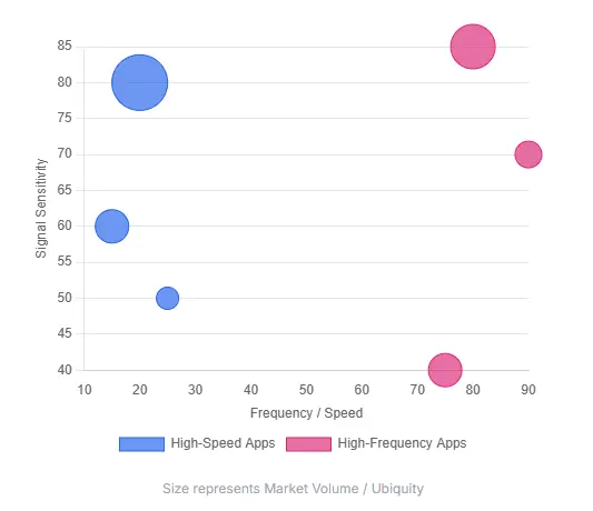
Typical Applications
Where do these technologies live? High-Speed powers computational logic, while High-Frequency powers wireless communication and sensing.
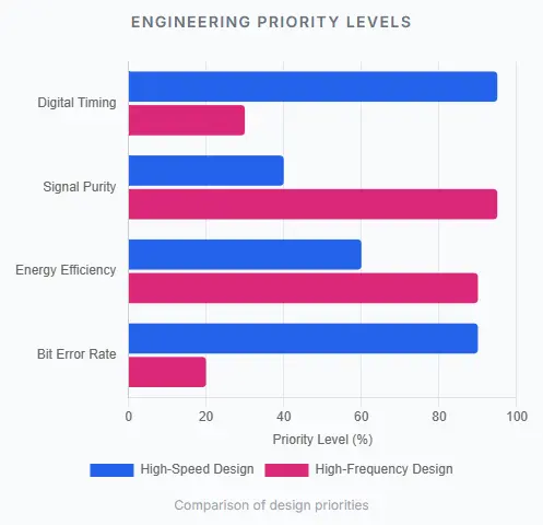
What metrics keep you up at night?
Many designers think high speed is defined by clock frequency (MHz/GHz). This is a myth. High speed is actually defined by the Rise Time of the signal. Even a lower frequency clock can be considered "high speed" if the edge transition (rise/fall time) is extremely fast, creating high-frequency spectral content that requires strict impedance control.
In RF worlds, every decibel (dB) counts. The primary enemy is signal attenuation caused by the PCB material itself.
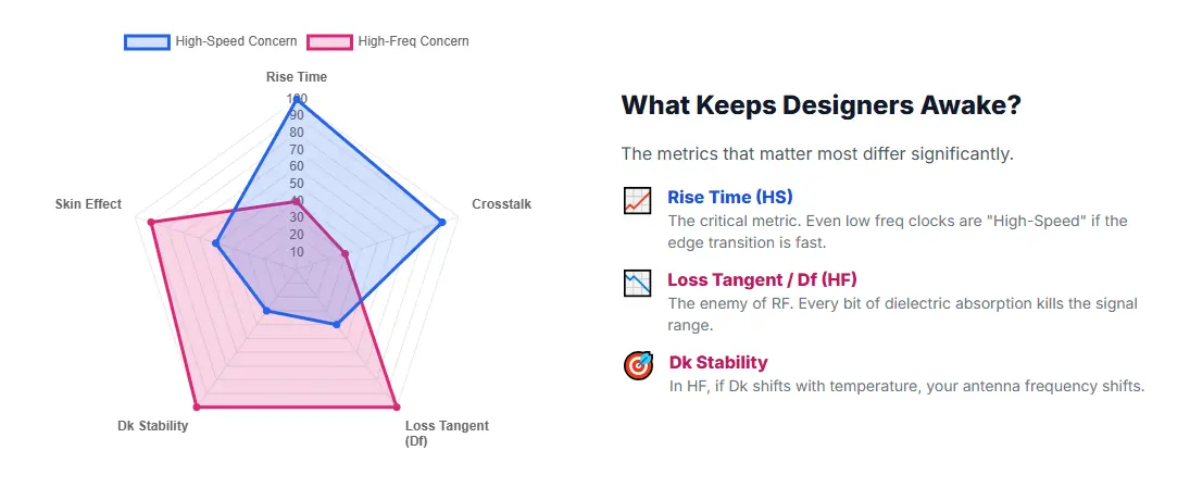
The metrics that matter most differ significantly.
This is where the distinction impacts your manufacturing bill of materials (BOM).
You generally need materials with a Low Coefficient of Thermal Expansion (CTE) and excellent mechanical stability to support multi-layer stacking (12+ layers) and high-density interconnects (HDI). Modified FR-4 or mid-loss materials often suffice, provided the impedance is controlled.
Standard FR-4 is usually a "no-go" because it absorbs too much signal energy at microwave frequencies. You need Specialized RF Laminates (like Rogers, Teflon/PTFE, or ceramic-filled hydrocarbons).
Material Selection Checklist
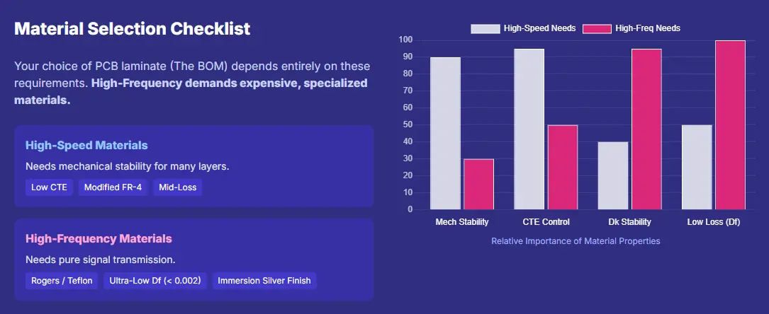
Your choice of PCB laminate (The BOM) depends entirely on these requirements. High-Frequency demands expensive, specialized materials.
If the technical details are still blurring together, visualize this analogy:
Imagine a massive 16-lane highway. Your job is to ensure thousands of sports cars (data bits) can drive side-by-side at 200 mph without crashing into each other (crosstalk) and arriving at the destination exactly on schedule. If the road is bumpy (impedance mismatch), the cars might spin out.
Imagine you are broadcasting a symphony. Your job is to ensure the sound wave travels through the air (or cable) without losing volume (loss) or getting distorted by static. You aren't managing thousands of cars; you are managing a single, perfect invisible wave to ensure it is caught clearly by a receiver miles away.
Whether you are routing DDR5 memory traces (High-Speed) or designing a 77GHz automotive radar array (High-Frequency), the success of your PCB begins with understanding the specific demands of your signal.
At NextPCB, we specialize in both. We offer advanced HDI fabrication for your high-speed computing needs and stock premium low-loss Rogers/Taconic materials for your RF projects.
Ready to build? Upload your Gerber files today for a free DFM check.

Still, need help? Contact Us: support@nextpcb.com
Need a PCB or PCBA quote? Quote now

