



Lolly Zheng- Sales Account Manager at NextPCB.com

 NextPCB Capabilities
Printed Circuit Boards
NextPCB Capabilities
Printed Circuit Boards
 PCB Assembly
 Layer Buildup
 SMD-Stencils
 PCB Design-Aid & Layout
 Mechanics
 Quality
 Drills & Throughplating
 Factory & Certificate
 PCB Assembly Factory Show
Certificate
PCB Assembly Factory Show
Certificate

Support Team
Feedback:
support@nextpcb.com


A 4-band resistor tells you two significant digits. A 5-band resistor tells you three — and that third digit is the difference between a component that's "close enough" and one that's precise enough for a voltage reference, a current-sense network, or a filter that has to hit a specific corner frequency. If you've ever squinted at five tiny bands under bad lighting and guessed wrong, you already know why this matters.
This guide walks through exactly how the 5-band system works, shows you how to use NextPCB's free 5-Band Resistor Color Code Calculator to decode any combination in seconds, and includes a full color reference table plus worked examples so you can double-check the math by hand. By the end, you'll be able to read a precision resistor at a glance — and know exactly when 5 bands actually matter versus when 4 is enough.
A 5-band resistor is an axial-lead resistor that encodes its value using five colored bands instead of the four found on general-purpose resistors. The first three bands represent significant digits, the fourth is a multiplier, and the fifth defines the tolerance — how far the real-world resistance is allowed to deviate from the printed value.
The extra digit isn't decoration. A 4-band resistor can only express two significant figures, so a value like 4.99 kΩ simply doesn't exist in that system — it rounds to 5.0 kΩ whether you like it or not. A 5-band resistor can express that third digit exactly, which is why precision resistors, metal film resistors, and anything specified to ±1% tolerance or tighter almost always use the 5-band format.
This matters most in circuits where the resistor sets a physical quantity rather than just limiting current: a voltage divider feeding an ADC reference, a current-sense resistor in a power supply feedback loop, a gain-setting resistor on an op-amp, or a filter network where the cutoff frequency has to land within a few percent of spec. In those circuits, a resistor that's "close" isn't good enough — it's out of spec.
Reading a 5-band resistor is mechanical once you know the order. Each band maps to a specific role, and the color of each band maps to a specific number:
Put together, the formula is straightforward:
Resistance = (D1 × 100 + D2 × 10 + D3) × Multiplier
Once you have the nominal resistance and the tolerance percentage from band 5, you can calculate the real-world operating range:
Minimum = R × (1 − Tolerance)
Maximum = R × (1 + Tolerance)
That range matters more than the nominal number in a lot of designs. A 10 kΩ resistor with ±1% tolerance is guaranteed to measure somewhere between 9.90 kΩ and 10.10 kΩ — and any circuit sensitive to that resistor's exact value needs to be designed to tolerate the whole range, not just the printed number.
This is the full color-to-value mapping used across all five bands. Note that black, orange, yellow, and white never appear as a tolerance band on standard 5-band resistors — if you see one of those colors in the fifth position, double-check you're reading the resistor in the correct direction.
| Color | Band 1 (D1) | Band 2 (D2) | Band 3 (D3) | Multiplier (Band 4) | Tolerance (Band 5) |
|---|---|---|---|---|---|
| Black | 0 | 0 | 0 | ×1 Ω | — |
| Brown | 1 | 1 | 1 | ×10 Ω | ±1% |
| Red | 2 | 2 | 2 | ×100 Ω | ±2% |
| Orange | 3 | 3 | 3 | ×1 kΩ | — |
| Yellow | 4 | 4 | 4 | ×10 kΩ | — |
| Green | 5 | 5 | 5 | ×100 kΩ | ±0.5% |
| Blue | 6 | 6 | 6 | ×1 MΩ | ±0.25% |
| Violet | 7 | 7 | 7 | ×10 MΩ | ±0.1% |
| Gray | 8 | 8 | 8 | — | ±0.05% |
| White | 9 | 9 | 9 | — | — |
| Gold | — | — | — | ×0.1 Ω | ±5% |
| Silver | — | — | — | ×0.01 Ω | ±10% |
A quick way to keep the digit sequence straight: Black, Brown, Red, Orange, Yellow, Green, Blue, Violet, Gray, White — 0 through 9 in order. It's the same mnemonic used for 4-band resistors, since bands 1–3 use identical color-to-digit mapping regardless of how many total bands the resistor has.
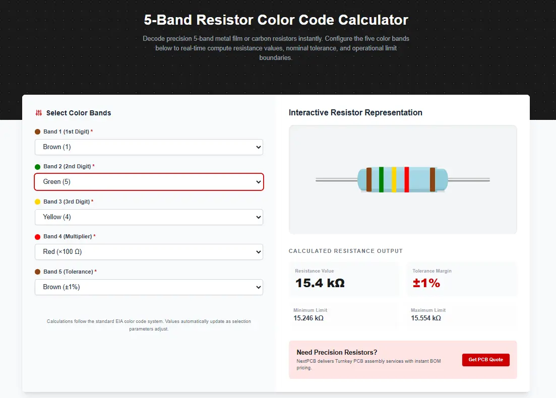
Manually working through the table above is fine for the occasional check, but it's slow and easy to mis-key when you're going through a parts bin or verifying a BOM. NextPCB's free 5-Band Resistor Color Code Calculator does the lookup and the math instantly:
The tool updates in real time as you select each band, returning the calculated resistance, the tolerance percentage, and — critically — the minimum and maximum resistance the physical part is guaranteed to fall within. That last part is what a lot of quick mental-math checks skip, and it's usually the number that matters most when you're debugging why a voltage divider or current-sense circuit is reading slightly off from the schematic value.
Try the 5-Band Resistor Color Code Calculator
Band 1 (Brown) = 1, Band 2 (Black) = 0, Band 3 (Black) = 0, Band 4 (Red) = ×100, Band 5 (Brown) = ±1%
Resistance = (1 × 100 + 0 × 10 + 0) × 100 = 100 × 100 = 10,000 Ω (10 kΩ)
Range at ±1%: 9.90 kΩ to 10.10 kΩ
Band 1 (Red) = 2, Band 2 (Yellow) = 4, Band 3 (Violet) = 7, Band 4 (Orange) = ×1,000, Band 5 (Brown) = ±1%
Resistance = (2 × 100 + 4 × 10 + 7) × 1,000 = 247 × 1,000 = 247,000 Ω (247 kΩ)
Range at ±1%: 244.53 kΩ to 249.47 kΩ
This is a good example of exactly why the third digit exists: 247 kΩ is a common precision value used in gain-setting and filter networks, and it simply cannot be represented on a 4-band resistor, which would round to either 240 kΩ or 250 kΩ — both well outside a ±1% tolerance window around the true target.
Band 1 (Green) = 5, Band 2 (Blue) = 6, Band 3 (Black) = 0, Band 4 (Gold) = ×0.1, Band 5 (Violet) = ±0.1%
Resistance = (5 × 100 + 6 × 10 + 0) × 0.1 = 560 × 0.1 = 56 Ω
Range at ±0.1%: 55.94 Ω to 56.06 Ω
This one shows the sub-1Ω multiplier range (gold and silver) in action, along with a tight ±0.1% tolerance typical of high-precision current-sense or calibration resistors.
All three formats share the same underlying color-to-digit logic; what changes is how many digits get encoded and whether temperature stability is specified on the resistor body itself.
| Format | Digit Bands | Typical Tolerance | Typical Use Case |
|---|---|---|---|
| 4-band | 2 (+ multiplier + tolerance) | ±5% or ±10% | General-purpose carbon film resistors |
| 5-band | 3 (+ multiplier + tolerance) | ±0.1% to ±2% | Precision metal film resistors |
| 6-band | 3 (+ multiplier + tolerance + TCR) | ±0.1% to ±1% | Precision resistors where thermal drift must be specified (adds a temperature coefficient band) |
The practical takeaway: if you're pulling a resistor for a non-critical role — a pull-up, an LED current limiter, general current limiting — a 4-band part at ±5% is almost always fine, and it's worth checking our 10k resistor guide for common pull-up and pull-down sizing. If the resistor sets a value the circuit depends on for accuracy, reach for a 5-band (or 6-band) part instead, and confirm the tolerance band matches what your design actually needs — specifying ±0.1% when ±1% would do just adds cost without a functional benefit.
This trips up more people than the color table itself. A resistor doesn't label which end is "Band 1," so you have to infer direction from physical clues:
If you're still unsure after checking spacing and color, decode it both directions in the calculator and see which result lands on a standard E96 value (the standard series used for 1%-tolerance resistors). Real-world 5-band resistors almost always land on a standard value — if one reading direction gives you an odd, non-standard number and the reverse gives you something like 4.99 kΩ or 10.2 kΩ, you likely had the direction backward.
Reading an existing resistor is one problem; specifying the right one for a new design is another. Once you know the exact resistance, tolerance, and power rating your circuit needs, that value has to make it cleanly from schematic to BOM to the assembled board without a substitution slipping through — which is where a lot of "it worked in simulation" designs run into trouble.
If your project is heading toward assembly, NextPCB's turnkey PCB assembly service sources passive components — including precision 5-band resistors — directly against your BOM, with component verification built into the process so the tolerance you specified is the tolerance that actually gets placed. For component sourcing on its own, HQ Online lets you check stock and pricing on specific resistor values before you finalize the design.
If the resistor you're sizing is going into a digital bus rather than an analog precision role, our companion guide on the I²C pull-up resistor calculator covers how to choose RP for reliable bus timing — a different sizing problem from the precision use cases covered here, but one that comes up just as often on the same boards.
A 4-band resistor encodes two significant digits, a multiplier, and a tolerance. A 5-band resistor adds a third significant digit, allowing it to express more precise values (like 247 Ω instead of rounding to 250 Ω) and typically pairing with tighter tolerances of ±1% or better.
The tolerance band is usually spaced slightly farther from the rest of the bands, and it's almost always gold, silver, brown, red, green, blue, violet, or gray — never black, orange, yellow, or white. If one end of the resistor is gold or silver, that end is almost certainly the tolerance band.
No — a genuine 5-band resistor always has five distinct bands. If you only see four clearly colored bands, you're most likely looking at a standard 4-band resistor, not a 5-band part with a missing band.
Standard resistor values follow the E96 series (for 1% tolerance) or E24 series (for 5% tolerance), which are logarithmically spaced sets of preferred values, not every possible number. If your calculated value doesn't land near a standard series value, double check the band order and colors — you may be reading the resistor in the wrong direction.
Yes, especially on older components exposed to heat, UV light, or handling oils. Faded brown can look orange-ish, and faded red can look closer to orange or pink. When a resistor's bands are ambiguous, verifying with a multimeter is faster and more reliable than guessing from a worn color.
The fifth band isn't a complication — it's precision. Once you can reliably separate the three digit bands from the multiplier and tolerance, reading a 5-band resistor takes the same few seconds as reading a 4-band one, just with a tighter, more specific answer at the end.
Use the 5-Band Resistor Color Code Calculator any time you need a fast, verified read on a component — whether you're auditing an inherited board, checking a pull from a parts bin, or double-checking a BOM before it goes to assembly. And when your design is ready to build, NextPCB's turnkey PCB assembly service sources and places the exact tolerance you specified, so the resistor on the schematic is the resistor on the board.
Get a PCB Assembly Quote Engineer Consultation

Still, need help? Contact Us: support@nextpcb.com
Need a PCB or PCBA quote? Quote now

