
 Surface


Julia Wu - Senior Sales Engineer at NextPCB.com

 NextPCB Capabilities
Printed Circuit Boards
NextPCB Capabilities
Printed Circuit Boards
 PCB Assembly
 Layer Buildup
 SMD-Stencils
 PCB Design-Aid & Layout
 Mechanics
 Quality
 Drills & Throughplating
 Factory & Certificate
 PCB Assembly Factory Show
Certificate
PCB Assembly Factory Show
Certificate
Support Team
Feedback:
support@nextpcb.com


A 10 kΩ resistor is a fundamental passive electronic component whose resistance value is 10,000 ohms (10 kilo-ohms). It is one of the most common and versatile resistance values in electronic circuits, widely used for current limiting, voltage division, biasing, and pull-up/pull-down functions. In many general applications, 10 kΩ strikes a practical compromise among current consumption, signal loading, and noise immunity. Printed circuit board (PCB) designs frequently incorporate this value—from checking 10 kΩ on a multimeter to integrating a 10 kΩ resistor in a circuit to control current and maintain predictable voltage levels.
Across both analog and digital domains, 10 kΩ components are used in voltage dividers, current limiters, biasing networks, filtering systems, and timing networks. In practice, they can serve as a protective element that keeps current within safe limits. Selecting 10 kΩ is often a pragmatic balance between desired current and required voltage control, based on specific circuit requirements.
This article goes beyond a simple definition to examine the advantages of the 10 kΩ value, its standardization and physical realization, and representative applications in analog and digital circuit design.
> Recommend reading: The Resistor in Modern Electronics: Fundamentals, Advanced Applications, and Reliability
Table of Contents
The consistent availability and low cost of 10 kΩ resistors are direct consequences of global component standardization. The value appears in preferred number series and is manufactured in all major form factors, giving engineers flexibility in production scale and density.
The E-series preferred numbers (E3, E6, E12, E24, E48, E96, E192) standardize resistance values and simplify inventory and manufacturing. Standardized by IEC 60063, the 10 kΩ value sits at a decade boundary and therefore appears in the E12, E24, and E96 series, facilitating selection and substitution.
While a 10 kΩ component with 1% tolerance (E96) can often substitute for 5%/10% applications, engineers must also verify temperature coefficient (TCR), voltage coefficient, pulse/surge capability, package size, and cost. Substitution should not rely solely on nominal tolerance. This cross-series availability helps consolidate inventory and reduce BOM complexity in high-volume products.
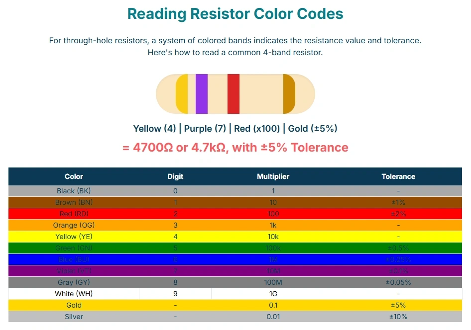
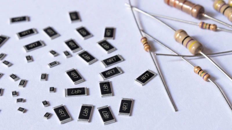
In axial (through-hole) resistors, color bands enable fast identification without measurement tools. For 10 kΩ:
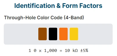
High-precision 6-band resistors add a sixth band for TCR. Note that SMD resistors typically use printed markings or no markings at all rather than color bands.
>Learn SMD Components: Definition, Types, and Identification Guide
| Tolerance | Banding Type | Band 1 | Band 2 | Band 3 | Multiplier | Tolerance Band | Code Sequence |
|---|---|---|---|---|---|---|---|
| ±5% | 4-Band | Brown (1) | Black (0) | N/A | Orange (×10³) | Gold (±5%) | Brown-Black-Orange-Gold |
| ±1% | 5-Band | Brown (1) | Black (0) | Black (0) | Red (×10²) | Brown (±1%) | Brown-Black-Black-Red-Brown |
10 kΩ resistors are available as axial (through-hole) parts and as rectangular SMD packages. Common SMD size codes are designated in both imperial and metric: 0603 (≈1608 metric), 0402 (≈1005), 0201 (≈0603), 01005 (≈0402).
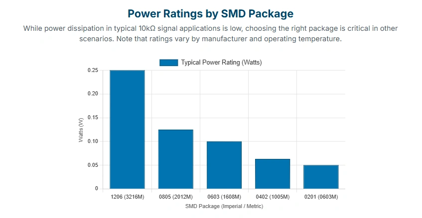
Package selection is driven by required power rating and manufacturing constraints. In many logic-level uses, power dissipation is minimal. For example, with 5 V across 10 kΩ, the dissipation is about 2.5 mW.
Typical SMD power ratings (manufacturer data/derating apply): 1206 ≈ 0.25 W, 0805 ≈ 0.125 W, 0603 ≈ 0.1–0.125 W, 0402 ≈ 0.063 W, 0201 ≈ 0.05 W. In addition to power, check operating voltage rating, pulse capability, assembly constraints, and maintainability. Because 2.5 mW is far below these ratings, dense footprints are often practical.
A 10 kΩ value offers a versatile impedance for analog tasks that require moderating current without excessive voltage loss or source loading.
A 10 kΩ resistor is commonly used for high-impedance limiting or isolation (e.g., input protection, weak pull-ups/downs). In a 5 V system, a simple estimate gives I ≈ V/R = 0.5 mA when the full supply appears across the resistor. This is useful for interfaces to microcontrollers and analog devices where low current and gentle loading are desired. However, LED indication and transistor drive typically require lower resistances (hundreds to a few thousand ohms, depending on target current and device β).
10 kΩ parts are widely used in voltage dividers and bias networks. They help set quiescent operating points for transistors and op-amps, and often appear in feedback networks to set gain. At a constant bandwidth, a resistor’s thermal noise voltage is proportional to √R. Choosing 10 kΩ is often a compromise among source impedance, noise, and power. If the following stage is sensitive to source impedance (e.g., some ADCs/op-amps), use datasheet limits to choose a lower equivalent source impedance.
Paired with capacitors, 10 kΩ resistors form RC filters with time constant τ = RC, enabling controlled cutoff frequencies for audio conditioning, anti-aliasing, and signal smoothing. The 10 kΩ scale works well with readily available μF-range capacitors to realize practical time constants.

10 kΩ resistors commonly appear with temperature sensors (e.g., thermistors) in dividers that convert temperature to voltage. If a sensor is rated 10 kΩ@25 °C, the divider resistor is selected per matching/linearization goals; it need not be 10 kΩ. Selection should consider the thermistor’s parameters (β/curve), target temperature range, and the front-end input characteristics.
In a monostable (one-shot) 555, the output pulse duration t is set by an external timing resistor R and capacitor C. A typical configuration connects R from VCC to DISCH (Pin 7), and C from Pin 7 to ground; THRES (Pin 6) monitors the capacitor voltage at Pin 7. The circuit resets when the capacitor reaches about 2/3 VCC. The trigger input TRIG (Pin 2) is momentarily driven low to start the timing cycle. The pulse duration is approximately t ≈ 1.1 RC.
Mechanical switch bounce is typically 10–50 ms. For debouncing around 25 ms, using R = 10 kΩ and C = 2.2 μF yields t ≈ 1.1 × 10 kΩ × 2.2 μF ≈ 24.2 ms, sufficient to cover most bounce without noticeable UI delay.
Table 2. 555 Timer RC Example (10 kΩ)
| Parameter | Symbol | Value | Units | Role |
|---|---|---|---|---|
| Timing Resistor | R | 10,000 | Ω | Charging/discharge resistance |
| Timing Capacitor | C | 2.2 | μF | Sets capacitance |
| Output Pulse Duration | t | ≈24.2 | ms | Debounce pulse width |
Digital inputs must be driven HIGH or LOW; floating inputs are susceptible to noise. A pull-up connects the pin weakly to VCC, holding HIGH when inactive and allowing external devices to pull LOW safely. A 10 kΩ value is a common starting point for buttons and general inputs. For I²C/SMBus, however, the pull-up must be calculated from bus capacitance and data rate: 10 kΩ may suffice for 100 kHz with short traces/low capacitance, while 400 kHz or higher-capacitance buses typically require 4.7 kΩ or lower. For the full calculation method and a quick-reference table by bus speed, see our I²C pull-up resistor calculator guide.
With a 5 V supply and 10 kΩ pull-up, the current when the line is driven LOW is ≈0.5 mA (≈2.5 mW). When idle HIGH, DC current is near zero; average power depends on LOW-level duty cycle.
Why is 10 kΩ used for I²C pull-ups?
10 kΩ is a power-friendly value suited to Standard Mode (100 kHz) and low-capacitance buses. Higher speeds or larger bus capacitance require lower resistance — see our I²C pull-up resistor calculation guide for the exact formula and values.
What power rating is required for a 10 kΩ resistor?
In low-voltage logic (e.g., 5 V), 10 kΩ dissipates about 2.5 mW—well below common 1/4 W ratings. For mains/high-voltage division or surge environments, verify rated power, operating voltage, creepage/clearance, and safety standards; do not apply low-voltage rules of thumb.
How does a 10 kΩ resistor help in timing circuits?
As the timing resistor R in RC networks (e.g., 555), it sets t ≈ 1.1RC, enabling practical delays (e.g., ≈24.2 ms) with compact μF-range capacitors.
Can I substitute a 10 kΩ resistor?
Yes, but recalc based on function. Lower values (e.g., 1 kΩ) improve noise margin/edge rates at higher current; higher values (e.g., 100 kΩ) reduce current but may compromise logic stability or timing.
Are 10 kΩ resistors polarized?
No. Fixed resistors are non-polarized and can be installed in either orientation.
Can I measure 10 kΩ with a multimeter?
Yes. Set the meter to resistance and measure across the leads; the meter shows the actual value.
Why use 10 kΩ vs. 2.7 kΩ?
Different values meet different goals: precise division, target current, bias point, or RC time constant. Choose per circuit requirements.
Can MCU internal pull-ups replace external 10 kΩ?
MCU internal pull-ups (typically ~20–50 kΩ) are fine for low-speed, low-power tasks (e.g., key scanning). For higher noise immunity, I²C, or precise interfaces, they’re usually too high; use external 10 kΩ or smaller values as required.

The 10 kΩ resistor remains a mainstay of electronic design due to its standardized availability and functional versatility. It is easy to identify (in axial parts via color bands) and, being non-polarized, simple to integrate.
>> Recommend: Current Sense Resistor: Low Ohm Shunt Selection, PCB Layout and Kelvin Connection

Still, need help? Contact Us: support@nextpcb.com
Need a PCB or PCBA quote? Quote now

