
 Surface


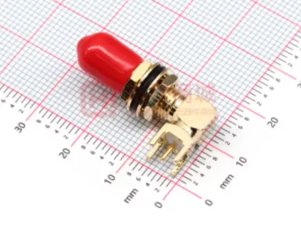
HJ-SMA020: Mechanical dimensions and PCB layout reference for a typical edge-mount right-angle SMA connector.

 NextPCB Capabilities
Printed Circuit Boards
NextPCB Capabilities
Printed Circuit Boards
 PCB Assembly
 Layer Buildup
 SMD-Stencils
 PCB Design-Aid & Layout
 Mechanics
 Quality
 Drills & Throughplating
 Factory & Certificate
 PCB Assembly Factory Show
Certificate
PCB Assembly Factory Show
Certificate
Support Team
Feedback:
support@nextpcb.com


With the rapid expansion of 5G-A networks, aerospace communications, and industrial IoT, the demand for reliable high-frequency signal transmission is at an all-time high. At the heart of these complex RF (Radio Frequency) systems lies a critical component: the SMA connector.
But what exactly makes the SMA connector the industry standard for high-frequency applications? And more importantly, how can you ensure your PCB design is optimized to support its full potential?
In this comprehensive guide, we will dive deep into the technical specifications of the SMA connector, clarify common confusions (like SMA vs. RP-SMA), and share expert PCB layout tips to maintain signal integrity.
SMA stands for SubMiniature version A. Developed in the 1960s, it is a semi-precision coaxial RF connector designed to provide a secure and highly reliable connection for high-frequency signals. Characterized by its threaded coupling mechanism (1/4-36 thread), the SMA connector ensures a tight, uniform contact that minimizes signal reflection and loss, even in environments subject to severe vibration in RF and microwave applications.
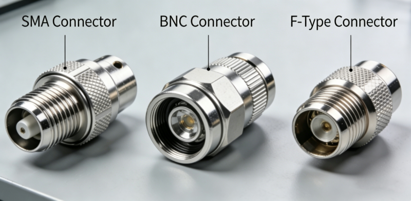
To understand why engineers default to the SMA connector, we need to look at its core technical features and application scenarios:
One of the most common pain points for procurement and hardware engineers is mixing up standard SMA and RP-SMA (Reverse Polarity SMA).
The Reverse Polarity SMA connector (RP-SMA) changes the gender of the internal center contact (swapping the center pin and center hole), while maintaining the original construction of the shell and its threads. RP-SMA was introduced to reduce compatibility with standard SMA interfaces in consumer wireless equipment. By reversing the center contact polarity, it reduces the chance of accidental mating with standard SMA connectors.
In RF connectors, gender is typically determined by the internal electrical components. RP-SMA prevents mismatching with standard SMA connectors by "reversing" this relationship. RP-SMA Male (Plug): has the same inside-threaded shell as a standard male, but instead of a center pin, it has a center receptacle (Socket). RP-SMA Female (Jack): has the same outside-threaded shell as a standard female, but instead of a receptacle, it has a center pin.
Here is a detailed comparison:
| Connector Type | Shell Thread Position | Center Contact Structure | Common Application Scenario |
|---|---|---|---|
| Standard SMA Male | Inside Threads | With Pin | RF Communication Modules, Cellular Antennas |
| Standard SMA Female | Outside Threads | With Hole (Receptacle) | PCB Board-end Interfaces, RF Test Instruments |
| RP-SMA Male | Inside Threads | With Hole (Receptacle) | Wi-Fi Router Antenna Ports |
| RP-SMA Female | Outside Threads | With Pin | Wi-Fi Terminal Antennas, Consumer Wireless Devices |
The emergence of RP-SMA was primarily to meet specific regulatory requirements, such as FCC Part 15:
Choosing the right SMA connector is only half the battle. If your PCB layout is flawed, you will experience severe insertion loss, impedance mismatch, and high VSWR (Voltage Standing Wave Ratio).
The trace connecting the SMA connector to the RF circuit should be designed for a controlled 50-ohm impedance. Depending on your PCB stackup, you will need to design a Microstrip or Coplanar Waveguide (CPW) trace. Use a reliable impedance calculator to determine the exact trace width and spacing.
>> Browse NextPCB Multi-layer PCB Stack-up Design & Impedance Control Solutions
| Ensure 50Ω Impedance Match for Your SMA Connector Layout |
SMA connectors demand a precisely matched 50Ω transmission line right to the launch point. Use NextPCB's stackup configurator to confirm trace width and dielectric thickness before sending your files.
The soldering pad for the SMA center pin can act as a parasitic capacitor, which degrades high-frequency performance.
For edge-mount or through-hole SMA connectors, a solid ground connection is paramount. Surround the RF signal trace and the connector’s ground pins with a "picket fence" of ground vias. This ties the top and bottom ground planes together, preventing electromagnetic radiation and suppressing unwanted resonances.
At frequencies above 3 GHz, standard FR4 material begins to show significant dielectric loss. For optimal SMA connector performance in high-frequency applications, consider using specialized RF laminates like Rogers, PTFE, or High-Tg materials.
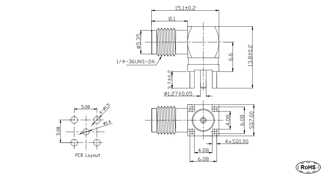
HJ-SMA020: Mechanical dimensions and PCB layout reference for a typical edge-mount right-angle SMA connector.
The reason SMA connectors remain highly competitive in 2026 stems from their balance of technical performance, compact size, application adaptability, and supply chain maturity:
In 2026, SMA has become a standard across industries:
When building high-frequency devices, component authenticity and precise manufacturing are non-negotiable.
Where to source quality SMA connectors? If you need reliable components with transparent pricing and real-time inventory, we recommend checking out HQ Online. You can visit the HQ Online SMA connector search page to secure the best parts for your project.
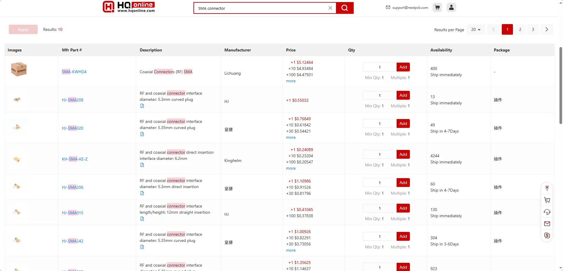
You can easily search for and purchase genuine SMA connectors of various specifications on HQ Online.
Where to manufacture your high-frequency PCB? An SMA connector is only as good as the board it's mounted on. At NextPCB, we specialize in advanced PCB manufacturing tailored for RF and microwave applications.
NextPCB provides professional RF PCB manufacturing, supporting high-frequency materials and ±5% precision impedance control.
>> Read more: RF PCB Routing Design: Physical Layout to Manufacturing-Driven Impedance Control
The SMA connector is the universal standard interface in the high-frequency RF field, with applications ranging from consumer Wi-Fi routers to professional aerospace radar systems. During design and implementation, verifying technical specs like frequency range and impedance, accurately identifying Standard vs. RP-SMA interfaces for compatibility, and strictly executing 50 Ohm impedance matching in PCB layouts will effectively reduce signal reflection (VSWR) and minimize insertion loss.
Ready to bring your RF design to life? Choose reliable components and ensure your PCB manufacturing and assembly are optimized for high-frequency performance.
Still, need help? Contact Us: support@nextpcb.com
Need a PCB or PCBA quote? Quote now

