
 NextPCB Capabilities
Printed Circuit Boards
NextPCB Capabilities
Printed Circuit Boards
 PCB Assembly
 Layer Buildup
 SMD-Stencils
 PCB Design-Aid & Layout
 Mechanics
 Quality
 Drills & Throughplating
 Factory & Certificate
 PCB Assembly Factory Show
Certificate
PCB Assembly Factory Show
Certificate
Support Team
Feedback:
support@nextpcb.com


Opening Note: The Industry Logic Behind Software Choices
PCB design software usually centers on two core modules: schematic capture and PCB layout/routing. The mainstream tools engineers rely on today did not appear by accident. Altium, Cadence, and Mentor Graphics (now under Siemens) each went through a long history of mergers, acquisitions, and continuous product evolution.
From early specialization in narrow segments to market consolidation through competition and integration, the ecosystem eventually converged on three widely used platforms: Altium Designer (originating from Protel), Cadence Allegro, and PADS (originally from Mentor Graphics). These tools differ in positioning and emphasis, but the design philosophy behind them is closely related. Once you master one of them, learning the others becomes much easier.
Software is only the tool; design thinking is the real core. Before diving into each platform, one point deserves special emphasis: no matter which software you use, stackup structure and impedance control are the foundation of high-speed PCB design. If you are planning a stackup scheme, you can use the NextPCB impedance calculator for an initial check, then refine your routing rules based on simulation results for a more efficient workflow.
https://www.altium.com/altium-designer
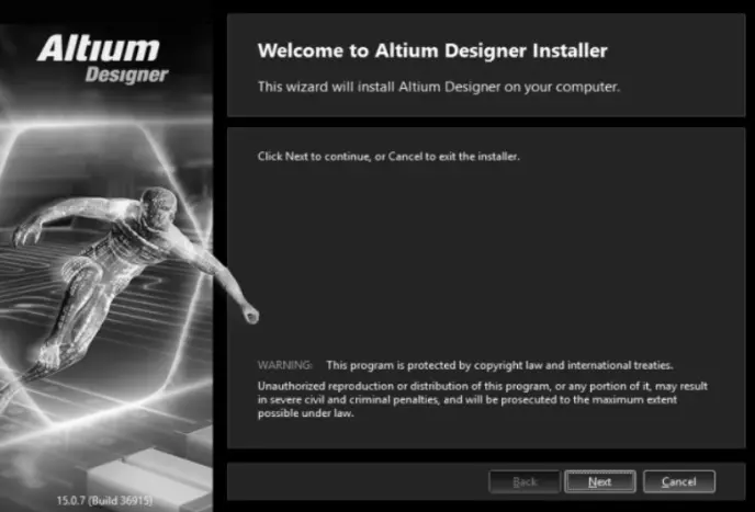
The initial welcome screen for the Altium Designer installation wizard.
Altium Designer fully inherits the features and strengths of earlier versions such as Protel 99 SE and Protel DXP, while introducing substantial improvements and high-end design capabilities. It breaks away from the traditional board-level design interface by integrating FPGA design and SOPC implementation into one platform, allowing engineers to carry system design, PCB design, and embedded development forward in the same environment. The trade-off is clear: Altium Designer also places higher demands on computer hardware.
Among engineers, Altium Designer is widely known for being easy to learn and user-friendly, making it especially suitable for small and mid-sized teams as well as individual developers. However, in complex high-speed multilayer board designs, the software can consume significant system resources, and earlier versions were sometimes criticized for sluggish routing performance. That issue has been gradually improved in later releases.
| Module Name | Description |
|---|---|
| (1) Schematic design | The schematic design system consists of the schematic editor (SCH), the component library editor (SCHLib), and a text editor. It supports schematic creation and editing, library maintenance and updates, and the viewing and export of various reports. |
| (2) PCB design | The PCB design system consists of the PCB editor, the footprint editor (PCBLib), and the board component manager. It covers PCB creation and modification, footprint library management, and manufacturing file generation, including Gerber files, drill files, solder mask layers, silkscreen layers, and more. |
| (3) Circuit simulation | A built-in digital/analog mixed-signal simulator can be used to simulate schematics and verify logical correctness and signal feasibility. |
| (4) FPGA and logic device design | The programmable logic design system includes a syntax-aware text editor and waveform editor, supporting logic circuit analysis and synthesis, waveform inspection, and PLD logic minimization and optimization. |
| (5) Embedded software development | It provides a complete embedded software development environment, including an editor, compiler, generator, linker, and debugger, with support for a processor-independent Viper C compiler and full source-level debugging. |
| (6) 3D PCB design | Altium Designer offers native 3D PCB editing, including the ability to import mechanical enclosure STEP models and perform accurate 3D design rule checks. As PCB density continues to increase, 3D viewing has become a practical tool for identifying potential issues in high-density multilayer boards, while also enabling seamless ECAD-MCAD collaboration. |
| (7) Advanced signal integrity analysis | The signal integrity analysis module provides a precise simulator for analyzing issues such as overshoot, impedance matching, and signal harmonics in PCB designs, enabling early-stage verification during high-speed design. |
| Feature Category | Details |
|---|---|
| Design Environment | Unified design environment: schematic and PCB work in the same interface, with the design state remaining synchronized in real time. |
| Routing & Copper | Interactive and guided routing (high-performance engine with real-time clearance display); Dynamic copper pours (custom polygon editing). |
| High-Speed & Advanced Design | High-speed design automation (DDR3, USB 3.0 length-matching); 3D PCB and rigid-flex support (native 3D checking, bend lines, flex regions). |
| Collaboration & Management | ECAD/MCAD collaboration (STEP import/export); Design variable management (derivative designs); Reuse support (circuit modules/templates). |
| Control & Documentation | Integrated version control (traceable changes); Draftsman documentation tools; Workflow-oriented design rule management. |
The development history of Altium Designer, to some extent, reflects the broader shift in PCB design tools from “good enough” to “all-in-one.” From a functional perspective, Altium Designer has continued moving toward high-speed design, high density, mixed hardware-software integration, team collaboration, and ECAD/MCAD cooperation. Its boundaries have expanded from single-board to multi-board, from low-frequency to high-speed, and from FPGA logic to 3D PCB workflows.
| Version | Major Updates / Innovations |
|---|---|
| Altium Designer 16 | Introduced partnership with CST, integrating electromagnetic field solver; added signal integrity and power integrity simulation. |
| Altium Designer 17 | Added 64-bit system support; enhanced interactive routing; advanced Layer Stack Manager; ActiveBOM. |
| High-Speed Update (xSignals) | xSignals mechanism: define paths with multiple nets/components as extended signals for high-speed rules; supports DDR3/DDR4; smart wizard for batch definition. |
| Altium Designer 20 | Optimized interactive routing (push function); high-speed support for DDR3/4/5, 100G Ethernet, PCIe 4.0/5.0; ActiveBOM 3D PDF documents; high-voltage creepage design rules. |
Overall, the sophistication of Altium Designer’s feature set comes with steadily increasing resource consumption, which has long been one of the key trade-offs faced by its development team between feature expansion and performance optimization.
https://www.cadence.com/en_US/home/tools/pcb-design-and-analysis/allegro-x-design-platform.html#allegro-x-pcb-designer
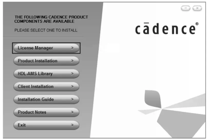
A centralized installation menu for various Cadence design suite components and utilities.
Cadence Design Systems is a major EDA company listed on NASDAQ in the United States under the ticker CDNC. It was formed in 1988 through the merger of SDA Systems and ECAD, and is one of the world’s largest providers of electronic design automation solutions.
Cadence’s solutions cover the full electronic design flow: system-level design, functional verification, IC synthesis and place-and-route, analog/mixed-signal and RF IC design, full-custom IC design, IC physical verification, PCB design, and hardware simulation modeling. Among these, its IC design, simulation, and verification tools are industry-leading. Its PCB design tool, Allegro, is positioned for high-end design scenarios and is highly regarded in the complex multilayer board segment.
Cadence entered mainland China in 1992 and subsequently established branches and R&D centers in Beijing, Shanghai, and Shenzhen. In 2008, it moved its Asia-Pacific headquarters to Shanghai. Cadence’s Beijing R&D center handles EDA software development tasks for the U.S. headquarters, while the China team also provides full-flow technical support, ranging from system simulation and verification to digital front-end/back-end, mixed RF front-end, SiP packaging, and PCB design.
By integrating schematic design, circuit simulation, PCB editing, topology-driven automatic routing, signal integrity analysis, and design output into one flow, Allegro builds a complete design chain for complex, large-scale circuit boards. Among the three mainstream software platforms, Allegro has a relatively steep learning curve, but its rigorous constraint system and powerful signal integrity analysis capabilities give it a unique advantage in high-end PCB design.
It is widely used in industries with demanding signal quality requirements such as communications, servers, and high-speed networking.
In high-speed PCB design, stackup structure and impedance control are often among the most critical factors determining success or failure. Allegro supports detailed stackup parameter settings, and it works best when paired with impedance calculation tools. If you are planning a stackup, you can use the NextPCB impedance calculator to quickly verify impedance results under different stackup configurations and use those results as a reference for constraint definition.
Allegro 17.4 is one of the more representative recent versions, with systematic improvements in user experience and performance. The main updates include the following.
| Category | Feature Details |
|---|---|
| UI & Usability | Optimized interface themes (Dark theme); Toolbar redesign and customization; Multi-screen support (drag schematic to 2nd screen). |
| Project Management | Improved Project Manager (multi-project support); Unified output window for messages/errors; Independent "Find" window. |
| Design Workflow | Direct PCB creation from schematic; Design Sync (real-time comparison/sync between SCH and PCB without ECO files). |
| Compatibility | 17.2 compatibility mode (open older files without automatic upgrade). |
| 3D Visualization | Enhanced 3D display (selective elements); Cutting Plane access; Mechanical enclosure transparency; DFA Bound support; Solder paste Z-axis thickness; Memory optimization (3d_canvas_skinning). |
| PCB Design Functions | Via Array integration (Add/Delete/Update unified); Refined pad/via connection (layer-independent thermal settings); Expanded Keepout layers (Outer/Inner/Plane options); Unlimited mechanical layers; Enhanced Copy/Paste (cache storage, polar mode). |
https://www.siemens.com/en-us/products/pcb/pads/
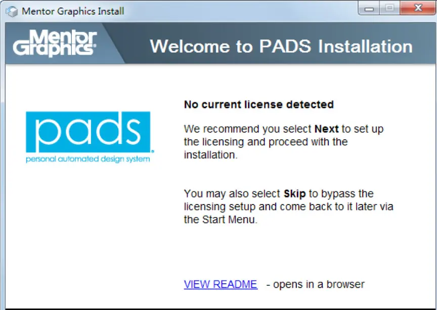
The opening license prompt for a PADS installation via the Mentor Graphics installer.
PADS (Personal Automated Design System) is centered on PCB tools. It was originally launched by PADS Software Inc., later acquired by Innoveda, and eventually became part of Mentor Graphics, where it served as the company’s main product line for the mid-range PCB design market. Mentor Graphics has since been acquired by Siemens, and the PADS product line continues to operate.
As a top-tier global EDA vendor, Mentor Graphics’ PADS series has long followed a product philosophy of powerful functionality and simple operation, building a broad user base in electronic engineering design. It is one of the tools frequently used by circuit design engineers and technical staff, especially in China.
| Version Phase | Key Features & Changes |
|---|---|
| PADS 2005 / 2007 | PADS 2005: stable, basic. PADS 2007: Added pin-number display; sub-versions (PE, XE, SE) for different complexities; parameterized component database. |
| PADS 9.1 / 9.2 | PADS 9.1: Windows-based GUI; compatible with Protel/Expedition; RF design; hierarchical rules. PADS 9.2: Net name display in PCB; quick Layout/Router switching; Windows 7 support. |
| PADS 9.3 / 9.4 / 9.5 | PADS 9.3/9.4: Metric units; DxDataBook; Archiver tool. PADS 9.5: Latium-architecture fast interactive routing editor for advanced needs. |
| PADS VX.2.2 (2017) | Current main reference: Includes PADS Logic, Layout, Router, DxDesigner, IO Designer, and HyperLynx. Mainstream platform for complete design flow. |
The core positioning of PADS VX.2.2 is high-speed circuit design, with strong focus on high-speed routing constraints in both automatic and batch-processing modes. Its physical design environment is intended to serve as a clearly defined solution for high-speed circuit design.
| Functional Area | Details |
|---|---|
| (1) User Interface | PADS Logic: Graphical UI based on Latium architecture; customizable toolbars, shortcut keys, and Chinese-language support. |
| (2) Routing Engine | PADS Router: Automatic routing for differential pairs/length control; hierarchical constraint rules; network topology protection; high-pin-count device support with fallback spacing. |
| (3) Design Verification | PADS Layout/Router: Rules for min/max length, diff-pair clearance, and connection order; batch verification before output. |
| (4) Advanced Packaging | Advanced Packaging Toolkit: Support for bare-die components, wire bond placement, die flags, and power ring configuration for SoB design. |
| (5) Data & Simulation | Data exchange: Flow/Library conversion (Xpedition/Central Library); improved Altium import; PSpice converter updates; electrical net real-time sync; CAM integrity testing. |
PADS Logic serves as the schematic entry point for the PADS family. It is feature-complete and intuitive, providing efficient design data input for PADS Layout. PADS Layout/Router, meanwhile, is the core environment for complex high-speed PCB design. Built on a shape-based, rule-driven placement and routing approach, and combining automatic and interactive routing methods, it integrates the front-end and back-end tool chain, including test preparation and manufacturing. PADS Layout also supports Microsoft-standard programming interfaces and can integrate with other Windows toolsets through Visual Basic programs and OLE automation, making customized workflow development convenient.
| Software | Target Audience / Best Use Case | Learning Curve |
|---|---|---|
| Altium Designer | Small/Mid-sized teams, individual developers, unified environment lovers. Great for getting up to speed quickly. | Moderate / Easy |
| Cadence Allegro | High-end design (Communications, Servers, High-speed interfaces). Strict signal integrity requirements. | Steep |
| PADS | Consumer electronics, medical, communications. Mid-range market, stable operation, moderate resource usage. | Moderate |
No matter which tool you use, the stackup design of a high-speed multilayer board is foundational work that cannot be ignored. Stackup parameters determine differential impedance, characteristic impedance, and coupling effects, all of which directly affect routing rule definition. When planning a stackup, you can use the NextPCB impedance calculator in HQDFM to verify different stackup configurations and use the results as the basis for later constraint settings.
The design philosophies of these three software platforms are closely aligned. Once you master one, the cost of learning the others drops significantly. Software is the vehicle; design thinking is the real competitive advantage.
Q: Which software is best for beginners or individual developers? A: Altium Designer is generally considered the most beginner-friendly. Its unified interface and intuitive design flow make it easier to learn compared to the more rigid constraint systems of Allegro or the multi-tool environment of PADS.
Q: Can I open files created in one software with another? A: While each platform uses proprietary file formats, most offer import wizards. For example, Altium and Allegro both have tools to import PADS files, and PADS VX.2.2 has improved its ability to import Altium projects. However, some manual adjustment of constraints and rules is almost always required after conversion.
Q: Why is Cadence Allegro preferred for server and communication board design? A: High-end designs like servers involve extremely complex high-speed signals and dense multilayer stackups. Allegro’s strength lies in its sophisticated constraint manager and integrated signal integrity tools, which ensure that strict timing and impedance requirements are met across thousands of connections.
Q: Is there a significant difference in hardware requirements between these tools? A: Yes. Altium Designer, due to its "all-in-one" integration and native 3D engine, tends to be more resource-intensive and requires a more powerful GPU and more RAM for smooth performance. PADS is relatively lightweight, while Allegro’s performance depends heavily on the complexity of the design and the simulation modules being used.
Q: Does master of one software help in learning the others? A: Absolutely. While the keyboard shortcuts and menu layouts differ, the core logic—schematic capture, footprint creation, layer stackup management, and design rule checking—is fundamentally the same. The transition usually involves learning the specific interface and command syntax of the new tool rather than relearning PCB design principles.
Q: How important is external impedance calculation when the software has built-in tools? A: Built-in tools are excellent for real-time routing, but external calculators (like the NextPCB impedance calculator) provide a vital cross-check. They are often faster for initial "what-if" scenarios when planning your stackup before you have even started the layout, ensuring your physical design starts on a technically sound foundation.
Still, need help? Contact Us: support@nextpcb.com
Need a PCB or PCBA quote? Quote now


 Surface

