
 NextPCB Capabilities
Printed Circuit Boards
NextPCB Capabilities
Printed Circuit Boards
 PCB Assembly
 Layer Buildup
 SMD-Stencils
 PCB Design-Aid & Layout
 Mechanics
 Quality
 Drills & Throughplating
 Factory & Certificate
 PCB Assembly Factory Show
Certificate
PCB Assembly Factory Show
Certificate
Support Team
Feedback:
support@nextpcb.com


In 2026, the electronics manufacturing industry is facing a familiar bottleneck. Surging demand from AI infrastructure and new energy vehicles (NEVs) is consuming the global supply of high-capacitance, high-voltage MLCCs (Multilayer Ceramic Capacitors). Lead times for specific specifications are stretching beyond 40 weeks, and spot market prices are fluctuating by up to 300% above catalogue pricing.
For hardware engineers and procurement managers, finding a reliable MLCC alternative is a daily necessity. However, swapping a capacitor is never just about matching the capacitance and voltage rating. A poorly chosen substitute can lead to severe system instability, power filtering failures, or total device breakdowns in the field.
In this guide, we break down the core technical differences between MLCC dielectrics, decode the part number systems of major brands, expose the hidden trap of DC bias, and explain how a reliable Turnkey PCBA partner can reduce your supply chain risks.
Currently hardest to source: High-capacitance (≥10µF), high-voltage (≥25V) X7R parts in 0402–0603 packages are under the most pressure in 2026, driven by AI server build-outs and NEV production. Plan substitution strategies for these specifications first.
Table of Contents
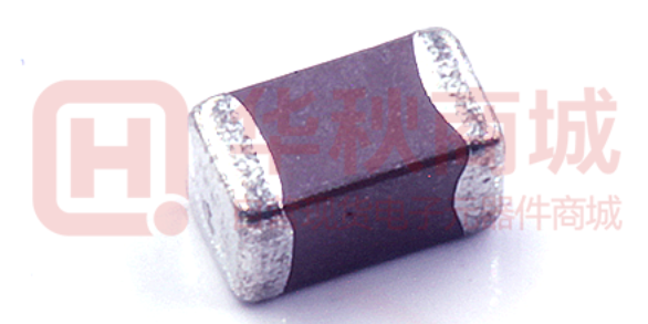
A typical surface-mount MLCC. Despite their uniform appearance, internal dielectric materials and DC bias performance can vary significantly between manufacturers, making precise cross-referencing essential for system stability.
When searching for an MLCC alternative, the first parameter to check after package size is the dielectric material. The dielectric determines how the capacitor behaves under temperature and voltage variations.
A common mistake is finding a cheaper equivalent that matches the capacitance and voltage but uses a lower-grade dielectric. As a general rule, an X7R capacitor should never be directly replaced with a Y5V unless the design has undergone complete temperature cycling, DC bias, and system-level validation.
For engineers evaluating components in the context of board-level design, understanding SMT PCB design principles is equally important when selecting dielectrics for surface-mount applications. Here is a clear breakdown of the most common MLCC dielectrics and their temperature characteristics:
| Dielectric Class | Material | Temp. Range (°C) | Capacitance Change (Max) | Typical Application |
|---|---|---|---|---|
| Class 1 | C0G / NP0 | −55 to +125 | ±30 ppm/°C (Virtually 0%) | RF circuits, timing circuits, oscillators. Extremely stable. |
| Class 2 | X7R | −55 to +125 | ±15% | Power supply decoupling, bypass, smoothing. Best balance of stability and capacitance density for general-purpose use. |
| Class 2 | X5R | −55 to +85 | ±15% | Consumer electronics, decoupling in space-constrained devices. |
| Class 2 | Y5V | −30 to +85 | +22% to −82% | General-purpose decoupling at room temperature only. Avoid in any critical circuit. |
The X7R vs. X5R consideration: While both offer a ±15% capacitance change, X7R operates reliably up to 125°C, making it suitable for automotive and industrial environments. X5R tops out at 85°C, which is generally sufficient for standard consumer electronics. Substituting an X7R with X5R is only viable if your product's thermal envelope is strictly controlled, validated, and guaranteed to stay below 85°C — including worst-case ambient temperature plus self-heating from nearby components.
Note for automotive designs: AEC-Q200 qualified designs almost always require X7R or C0G. Never substitute X5R in automotive applications without formal re-qualification.
To find a reliable Murata substitute or TDK equivalent, you must understand how manufacturers construct their part numbers. Every character encodes a critical specification: dimensions, voltage, capacitance, tolerance, and packaging.
Here is a detailed breakdown of the industry-standard Murata GRM series as a reference example:
Example Part Number: GRM 18 8 R7 1C 105 K A01 D
Note: Always refer to the manufacturer's specific series reference table, as naming conventions and character meanings vary by series and brand.
When crossing this to a TDK, Samsung, or Yageo part, procurement must align all five core parameters: Size (0603) · Dielectric (X7R) · Voltage (16 V) · Capacitance (1 µF) · Tolerance (±10%).
The table below shows common cross-reference examples across major brands:
| Murata (GRM) | TDK (CGA) | Samsung (CL) | Yageo (CC) | Key Parameters |
|---|---|---|---|---|
| GRM188R71C105K | CGA3E2X7R1C105K | CL10B105KA8NNNC | CC0603KRX7R9BB105 | 0603 · X7R · 16V · 1µF · ±10% |
| GRM21BR71H104K | CGA4J3X7R1H104K | CL21B104KBCNNNC | CC0805KRX7R9BB104 | 0805 · X7R · 50V · 100nF · ±10% |
| GRM31CR61A476M | CGA5L3X5R1A476M | CL21A476MQCLRNC | CC1206MRX5R7BB476 | 1206 · X5R · 10V · 47µF · ±20% |
* Always verify against current manufacturer datasheets before approving any substitute. Part numbers and availability change frequently.
Pro Tip: Always verify the thickness dimension. A substitute MLCC that is thicker than the original can cause issues during Pick-and-Place (SMT) assembly or interfere with mechanical enclosures and adjacent components on densely populated boards. Before finalizing any substitute, it is also worth reviewing capacitor detection methods to validate parts on arrival.
You matched the size, capacitance, voltage rating, and dielectric perfectly. Is the substitute guaranteed to perform equivalently in real operating conditions? Not necessarily. This is where many engineering teams fall into a costly trap: DC bias degradation.
High-dielectric-constant Class 2 MLCCs (X7R, X5R, and Y5V) experience a phenomenon where their effective capacitance decreases significantly as applied DC voltage increases. The nominal value on the component reel is measured at 0 V — not at your operating voltage.
A real-world scenario: You design a 5 V power rail and need 10 µF of capacitance for stability. You specify a quality brand's 10 µF, 6.3 V, X5R capacitor. At a 5 V load, this specific part might retain 6 µF of effective capacitance — enough to keep the system stable.
Now substitute it with an unverified generic equivalent with the same nominal specs. Under the same 5 V bias, that generic part might drop to only 2 µF — an 80% loss. The power supply ripples, voltage drops, and the result is unstable system behavior or intermittent field failures. For a deeper look at how decoupling capacitor selection affects rail stability, see our guide on power integrity design in PCB layout.
Why package size makes DC bias worse: Smaller package sizes exhibit more severe DC bias effects due to reduced dielectric volume. A 10 µF in 0402 will lose far more capacitance under bias than the same 10 µF in 0805. This is a critical consideration when substituting with a smaller footprint to save board space.
Secondary parameters that also vary between manufacturers:
| Parameter | Why It Matters | Where to Find It |
|---|---|---|
| DC Bias Curve | Effective capacitance at operating voltage — the most critical check | Manufacturer datasheet / SPICE model |
| ESR | Affects power dissipation and ripple filtering at high frequencies | Datasheet impedance curves |
| Ripple Current Rating | Safe operating current in power supply applications | Datasheet absolute maximum ratings |
| Aging Rate | Class 2 ceramics lose capacitance over time; rate varies by manufacturer | Datasheet — typically expressed as % / decade hour |
The takeaway: When approving an MLCC alternative, always check the manufacturer's datasheet for the specific DC bias curve at your operating voltage. If the substitute's datasheet does not include a DC bias curve, reject it. Never assume two capacitors with identical nominal specifications will perform identically under real operating conditions. High-frequency designs face additional challenges beyond DC bias — see our guide on power supply noise analysis in high-frequency PCB design for further reading.
Finding the right alternatives, verifying datasheets, and securing stock from multiple vendors can paralyze your project timeline. In an era of component hoarding and spot market volatility, a fragmented sourcing strategy carries significant risk.
A well-managed Turnkey PCBA workflow consolidates PCB manufacturing, component sourcing, and assembly capabilities under one roof — reducing sourcing risk and shortening validation cycles.
>> Browse NextPCB's PCBA Capabilities
Only if your operating temperature stays reliably below 85°C and you have validated the DC bias curve at your operating voltage. Both X7R and X5R share a ±15% capacitance change specification, but X5R's upper limit is 85°C versus 125°C for X7R. For automotive, industrial, or any design with elevated ambient temperatures, X7R is the minimum acceptable specification.
This is the DC bias effect — a fundamental physical property of Class 2 ferroelectric dielectrics (X7R, X5R, Y5V). Under applied DC voltage, the crystal domains in the dielectric align, reducing the material's permittivity and therefore its capacitance. The effect is more severe in smaller packages, higher capacitance values, and lower voltage-rated parts operated close to their rated voltage. Effective capacitance can drop 30–80% depending on the specific part and operating voltage.
Match five parameters in order: package size including thickness, dielectric code, voltage rating, capacitance value, and tolerance. Then obtain and compare the DC bias curves from each manufacturer's datasheet before approving the substitute. Many distributor parametric search tools will surface candidates, but only the datasheet DC bias curve confirms true functional equivalence.
High-capacitance (≥10µF), high-voltage (≥25V) X7R parts in 0402–0603 packages are under the most pressure, driven by AI server infrastructure build-outs and new energy vehicle production. AEC-Q200 qualified automotive parts are also experiencing extended lead times. Standard 100nF / 10V / X7R / 0402 parts remain relatively available.
Y5V is only acceptable for non-critical, room-temperature bypass applications where the exact capacitance value is not important to circuit operation. Its capacitance can vary from +22% to −82% over its temperature range, and it exhibits severe DC bias degradation. Never use Y5V in timing circuits, precision filtering, or any node where capacitance stability matters.
Substituting an MLCC is an engineering decision, not just a procurement task. Understanding dielectric behaviors, decoding part numbers correctly, accounting for DC bias degradation under real operating voltages, and verifying secondary parameters like ESR are non-negotiable steps to maintaining product quality and reliability.
Don't let component shortages delay your product launch. Let the experts manage your BOM. Not sure if your design is ready for assembly? Read our introduction to DFM (Design for Manufacturability) before submitting. Ready to streamline your manufacturing? Upload your Gerber files and BOM to NextPCB today for a free DFM check and a Turnkey PCBA quote. Our system will help secure your parts and keep your production lines moving reliably. >> Learn more PCB manufacturing services at NextPCB
Still, need help? Contact Us: support@nextpcb.com
Need a PCB or PCBA quote? Quote now


 Surface

