



Julia Wu - Senior Sales Engineer at NextPCB.com

 NextPCB Capabilities
Printed Circuit Boards
NextPCB Capabilities
Printed Circuit Boards
 PCB Assembly
 Layer Buildup
 SMD-Stencils
 PCB Design-Aid & Layout
 Mechanics
 Quality
 Drills & Throughplating
 Factory & Certificate
 PCB Assembly Factory Show
Certificate
PCB Assembly Factory Show
Certificate

Support Team
Feedback:
support@nextpcb.com


A Flexible Printed Circuit Board (Flexible PCB, FPCB, or flex circuit) is a circuit board built on a bendable base material -- typically polyimide (PI) or polyester (PET) -- instead of the rigid FR-4 substrate used in standard PCBs. FPCB stands for Flexible Printed Circuit Board, and the term is used interchangeably with "flex circuit" and "flexible circuit board" across the industry.
Because the base film can flex, fold, and twist without breaking the conductive traces, FPCBs are used wherever a design needs to save space, reduce weight, or route a circuit around a tight or moving mechanical structure -- inside a folding phone hinge, a wearable device, a camera module, or a medical implant, for example. The technology has been used to interconnect electronics since the 1950s and today it is a standard building block in consumer electronics, automotive, medical, aerospace, and industrial equipment.
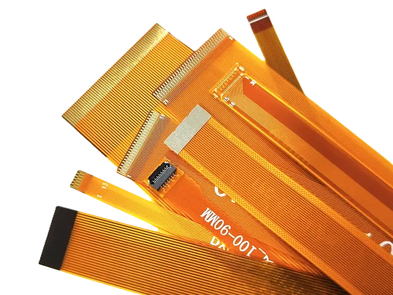
Engineers often need to decide quickly which board family fits a design. The table below compares the three main options at a glance.
| Attribute | Rigid PCB | Flexible PCB (FPCB) | Rigid-Flex PCB |
|---|---|---|---|
| Base material | FR-4 (glass-reinforced epoxy) | Polyimide (PI) or polyester (PET) film | FR-4 rigid sections + PI flex sections |
| Bendability | None | High -- can fold, roll, and flex repeatedly | Flex only in the designated flex zones |
| Typical thickness | 0.8–3.2 mm | 0.05–0.3 mm (single/double layer) | Varies by rigid + flex layer stack-up |
| Best for | Standard, static electronics | Space-constrained, moving, or wearable designs | Designs needing both structural mounting and dynamic flexing |
| Relative cost | Lowest | Higher than rigid due to materials and handling | Highest, due to combined processes |
| Assembly complexity | Low | Moderate to high | High |
For a deeper look at when to choose rigid-flex over a pure flex design, see our guide to Rigid-Flex PCBs, and for a full breakdown of inflexible vs. flex vs. rigid-flex boards, see Inflexible vs. Flex vs. Rigid-Flex PCBs.
Flexible PCBs are built as single-layer, double-layer, or multilayer circuits, but the single-layer FPCB illustrates the four core elements shared by all of them:
| Layer | Function | Common Material |
|---|---|---|
| Dielectric substrate film | Base material that carries the circuit | Polyimide (PI), prized for high-temperature resistance |
| Electric conductor | Carries the circuit traces | Rolled or electro-deposited copper foil |
| Adhesive | Bonds the conductor layer to the substrate | Polyimide adhesive or polyester adhesive |
| Protective finish (coverlay) | Insulates and protects the exposed circuit | Coverlay film or liquid photoimageable coating |
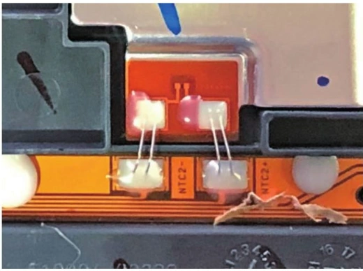
Flexible PCB with NTC thermistor sensors for automotive temperature sensing application
Polyimide is the dominant substrate for flex and rigid-flex circuits because it holds up better than epoxy resins under repeated movement, vibration, and elevated temperature. Polyester (PET) film is a lower-cost alternative, typically supplied 25–125 microns thick, with good electrical and chemical resistance but a lower maximum operating temperature than polyimide.
Copper foil -- either rolled-annealed or electro-deposited -- is the standard conductor. It is usually zinc-treated to resist oxidation and improve adhesion, and chemically treated foils further reduce bond degradation over the life of the board.
| Adhesive Type | Key Property | Typical Use Case |
|---|---|---|
| Polyimide adhesive | Wide temperature resistance, low coefficient of thermal expansion | Multilayer circuits, power generation, defense/military equipment |
| Polyester adhesive | Lower cost, lower bond strength, weaker fluctuating-temperature resistance | Cost-sensitive, less demanding thermal environments |
| Adhesiveless (all-polyimide) | Thinner stack-up, better dynamic flex-life, higher cost | Dynamic-flex, HDI, and fine-pitch applications |
| Type | Description |
|---|---|
| Single-sided circuit | One conductive copper layer accessible from a single side of the film |
| Single-sided with dual access | One conductive layer, but accessible from both the top and bottom surfaces |
| Double-sided circuit | Two conductive layers, one on each side of the base film, connected by plated through-holes |
| Multilayer circuit | Multiple single- and/or double-sided flex layers laminated together and interconnected through vias or bonded surfaces |
For a closer look at when a single-layer design is enough, see our Single Layer Flex PCB guide.
Rigid-flex boards combine rigid sections -- used to mount connectors, chassis, and heavier components -- with flexible sections that absorb vibration and allow folding. This hybrid construction improves reliability in designs that need both a stable mounting surface and dynamic movement in a single assembly.
High-Density Interconnect (HDI) flex boards use micro vias and finer trace geometries to pack more connections into a smaller footprint. The thinner substrate also improves electrical performance, which makes HDI flex circuits a common choice for compact, high-performance devices.
| Advantages | Disadvantages |
|---|---|
| Bends, folds, and winds to fit tight 3D spaces | More complex assembly process than rigid PCB |
| Reduces overall size and weight of the assembly | Harder and more costly to repair after a fault |
| Good heat dissipation and solderability | Higher risk of damage during handling |
| Strong signal integrity over a wide temperature range | Higher unit cost than an equivalent rigid PCB |
| High mechanical resistance and good EMI immunity | Sensitive to scratching and needs sulfur-free storage conditions |
Because polyimide is more expensive than FR-4 and requires more careful handling, the first stage focuses on efficient material use through techniques such as panel nesting. Key considerations at this stage include:
Hole sizes, filleting, and plating are controlled tightly at this stage:
| Cover Layer Option | Description |
|---|---|
| Adhesive-backed coverlay film | Best suited to dynamic-flex applications and general overcoating of custom circuits |
| Screen-printable liquid overcoat | A thicker polymer coating applied by screen printing |
| Photoimageable liquid/film polymer | Advanced solder mask option that blocks solder from unwanted traces, protects internal and external components, and guards against external electrical interference |
The table below summarizes NextPCB's current flexible PCB manufacturing specifications, so you can check feasibility before finalizing your design.
| Feature | Specification |
|---|---|
| Flex circuit layers | 1 to 6 layers |
| PI base material | Brands: ITEQ, Grace, Doosan, Allstar, Thinflex, and Taiflex Adhesive/adhesiveless RA or ED laminates |
| Covering type | PI coverlay or flexible solder mask |
| Surface finishes | ENIG, OSP, and electroplated gold |
| ENIG gold thickness | 1 to 3 μ" |
| Flex PCB thickness | 0.1 to 0.45 mm |
| Copper thickness | 1/3 to 2 oz |
| Min. trace width/spacing | 2/2 mil |
| Min. drill hole diameter | 0.1 mm |
| PCB solder mask color | Coverlay: yellow, white, black, and clear Solder mask: green, red, yellow, orange, black, silver, and clear |
| PCB stiffener options | FR-4, PI, aluminum, and stainless steel |
| Extras | EMI shielding, impedance control, custom stack-ups, laser or mold forming, conductive adhesive, 3M adhesive backing, and more |
| Industry | Typical Use Cases |
|---|---|
| Consumer electronics | Laptops, cameras, foldable/flip phones, calculators, wearables |
| Automotive | GPS units, engine control modules, airbag systems, anti-lock braking systems -- flex circuits cut weight and resist vibration better than wired harnesses |
| Medical | Pacemakers, hearing aids, fitness and heart-rate monitors, swallowable diagnostic capsules |
| Industrial | RF communication equipment, power circuits, industrial automation systems |
| Aerospace | RF communication, power distribution, control circuits, and compact sensor packaging |
| Military | High-precision, mission-critical systems that require rigorous quality control at every stage of fabrication and assembly |
| Power electronics | Designs that need thin copper conductors capable of carrying heavier currents |
| High-speed digital, RF, and microwave | Applications requiring reliable performance at high signal frequencies |
FPCB stands for Flexible Printed Circuit Board -- a circuit built on a bendable polyimide or polyester film instead of a rigid FR-4 base.
A flexible PCB is built entirely on a bendable substrate, while a rigid-flex PCB combines rigid FR-4 sections with flexible sections in a single laminated board, giving designers a stable mounting area alongside a dynamic flex zone.
The substrate is typically polyimide or polyester film, the conductor is copper foil, and the layers are joined with polyimide or polyester adhesive, or bonded directly in adhesiveless constructions.
Yes, the raw materials and assembly process for flex circuits generally cost more than an equivalent rigid PCB, though this can be offset over the product lifecycle by reduced wiring, connectors, and assembly labor.
Consumer electronics, automotive, medical devices, aerospace, military, and industrial automation are the heaviest users of flexible and rigid-flex circuit technology.
Flexible PCBs give designers a way to save space, cut weight, and route circuits through mechanical spaces that a rigid board simply cannot reach -- from a folding phone hinge to a swallowable medical sensor. Choosing between single-sided, double-sided, multilayer, or rigid-flex construction comes down to the mechanical movement, layer count, and reliability requirements of the specific application.
NextPCB manufactures single-sided, double-sided, multilayer, and rigid-flex PCBs to support projects from prototype through volume production. Our engineering team can help you choose the right stack-up, material set, and bend strategy for your design.
Ready to start your Flexible PCB project? Contact NextPCB for a quote, or explore our Flexible PCB manufacturing capabilities.

Still, need help? Contact Us: support@nextpcb.com
Need a PCB or PCBA quote? Quote now

