



Stacy Lu

 NextPCB Capabilities
Printed Circuit Boards
NextPCB Capabilities
Printed Circuit Boards
 PCB Assembly
 Layer Buildup
 SMD-Stencils
 PCB Design-Aid & Layout
 Mechanics
 Quality
 Drills & Throughplating
 Factory & Certificate
 PCB Assembly Factory Show
Certificate
PCB Assembly Factory Show
Certificate

Support Team
Feedback:
support@nextpcb.com


Introduction: Automated X-Ray Inspection in PCB Assembly
Automated X-Ray Inspection (AXI) has emerged as a cornerstone technology for ensuring structural integrity in modern printed circuit board assembly (PCBA). By utilizing high-energy X-rays rather than visible light, AXI automatically penetrates dense materials to inspect hidden internal features that traditional methodologies miss. As electronics undergo radical miniaturization, packages like BGAs and QFNs conceal their solder joints underneath the component bodies, making X-ray validation an indispensable part of high-yield assembly workflows. This in-depth technical guide breaks down the core physics of Automated X-Ray Inspection, compares 2D vs. 3D imaging capabilities, details the specific structural defects it diagnoses, and provides manufacturing guidelines to align with global IPC standards.
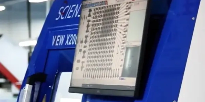
Automated X-Ray Inspection is a PCB testing method that uses X-ray imaging to automatically check assembled boards for defects hidden from normal view. In essence, X-Ray works on the same principles as Automated Optical Inspection (AOI), but uses X-rays as the imaging source instead of visible light. This allows X-Ray to “see” inside objects. X-rays are high-energy photons that penetrate materials; dense materials absorb more X-rays and appear darker in the image, whereas lighter materials let more X-rays through and appear lighter. By capturing an X-ray image of a PCB assembly and analyzing the shadows and contrasts, an X-Ray system can reveal internal structures and detect hidden flaws in solder joints, components, and PCB layers.
Automated X-Ray Inspection (AXI): A non-destructive testing (NDT) methodology that utilizes X-ray radiation to penetrate electronic assemblies, generating high-contrast digital images to automatically analyze and evaluate hidden internal structures—such as Ball Grid Array (BGA) connections, microvias, and layer alignment—against structural manufacturing tolerances.
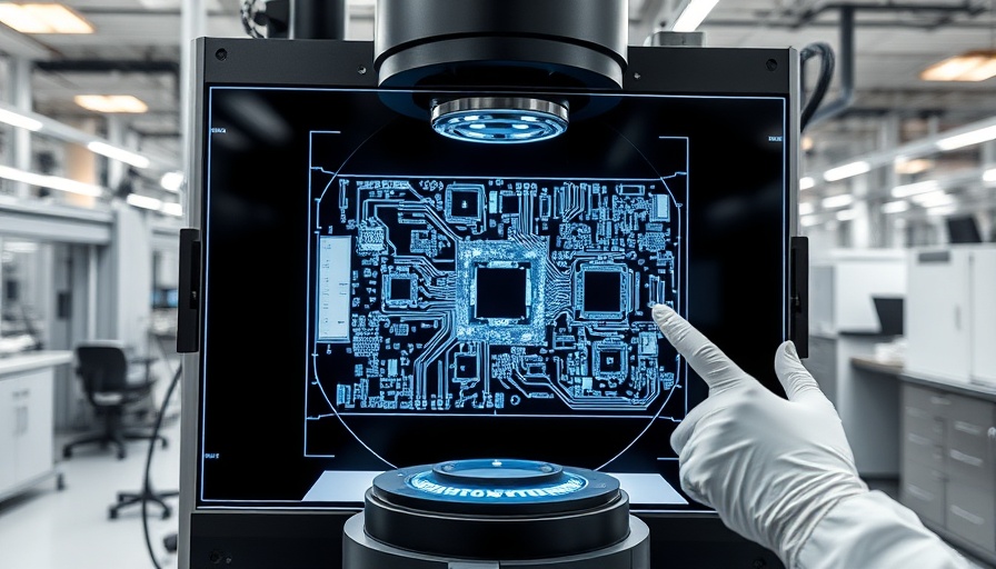
Modern X-Ray inspection equipment used for PCB quality control
Two-dimensional X-Ray systems provide flat, shadow-like images of PCB assemblies. These systems are cost-effective and suitable for basic inspection tasks, including:
Three-dimensional X-Ray systems, also known as computed tomography (CT) systems, provide detailed cross-sectional images and 3D reconstructions. These advanced systems excel at:
While both are automated inspection methods, AXI and AOI serve different and complementary purposes in the PCB assembly workflow. Here is a quick comparison:
| Feature | Automated Optical Inspection (AOI) | Automated X-Ray Inspection (AXI) |
|---|---|---|
| Inspection Source | Visible light and high-resolution cameras | High-energy X-ray photons |
| Primary Capability | Surface-level defects (missing parts, polarity, visible solder) | Hidden internal defects (BGA voids, inner-layer shorts) |
| Cost & Speed | Lower cost, very fast (ideal for 100% inline scanning) | Higher cost, slower (often used for complex parts/sampling) |
In an X-Ray system, an X-ray tube generates X-rays that pass through the assembled PCB. On the opposite side, a detector (or sensor array) captures the X-rays that emerge and converts them into a digital image.
Essentially, the PCB is "X-rayed" similar to how a medical X-ray works, but here the goal is to see hidden solder joints and internal connections. Heavy elements like metal (solder, copper) absorb more X-rays and thus appear as darker regions in the image, whereas lighter materials (fiberglass board, plastic component bodies) appear more transparent or lighter.
Specialized image processing software then analyzes these X-ray images to identify any anomalies or defects automatically, flagging them for repair or process adjustment. In an automated production environment, X-Ray machines can scan boards and use computer vision algorithms to decide pass/fail, much like AOI does with optical images, but looking at X-ray shadow images instead.
> Recommend Reading: PCB Assembly - The Most Comprehensive Guide | NextPCB
Ball Grid Array (BGA) and Chip Scale Package (CSP) components have solder connections hidden beneath the component body. X-Ray inspection is the only practical method to verify proper solder joint formation, detect bridging, and identify missing or misaligned balls without component removal.
Voids in solder joints can significantly impact thermal and electrical performance. X-Ray systems can detect, measure, and classify voids according to industry standards such as IPC-A-610, helping manufacturers maintain quality standards and prevent field failures.
X-Ray inspection serves as a critical quality control checkpoint in high-reliability applications such as aerospace, medical devices, and automotive electronics. It enables manufacturers to identify process variations and implement corrective actions before defective products reach customers.
One of the biggest advantages of X-Ray is its ability to detect soldering defects and assembly issues that are hidden or internal, which other inspection methods might miss. Let’s break down the typical defects X-Ray can identify in PCB assemblies.
X-Ray excels at inspecting solder joints, especially for surface-mount devices. It can easily detect solder bridges (unintended solder connections between pads or pins that cause shorts) even if they occur under packages or between BGA balls, where optical inspection can’t see.
It can also find solder opens/insufficient solder, where a joint didn’t form properly (e.g., a BGA ball not connecting to its pad, or an insufficient amount of solder paste leading to a weak joint). Solder shorts and solder splashes are visible as irregular dark connections in X-ray images, allowing X-Ray to catch shorts that might be hidden under components.
Voids are trapped air or gas pockets within a solder joint – these appear as lighter spots or “bubbles” in the dark solder area on an X-ray image (since air/gas is much less dense than metal). X-Ray inspection is one of the only practical ways to identify solder voids non-destructively.
While a few small voids can be acceptable, excessive voiding (e.g. covering >25% of the joint area) is a reliability concern; X-Ray can measure void sizes and percentages to ensure they’re within IPC standards. Porosity and slag inclusions (tiny voids or foreign material in solder) also show up clearly in X-rays as bright or mottled areas within joints.
For BGAs and CSPs (chip-scale packages), X-Ray is the go-to inspection method. It can find missing balls, misaligned balls, BGA shorts (two balls bridged underneath), and BGA open connections (ball not soldered to pad). It can also reveal head-in-pillow (HIP) defects in BGAs – a subtle issue where the solder ball and paste didn’t fuse, leaving a gap.
HIP defects are essentially an open in the vertical axis and are very hard to catch with anything except X-ray or CT slices. A 3D X-Ray (CT) image will show a head-in-pillow as a clear separation between the ball and pad in cross-section. X-Ray is invaluable for ball grid array inspection to ensure all those hidden joints are solid.
Components like QFNs or LGA (land grid array) packages have pads only on the underside. X-Ray can check these hidden solder fillets for issues like insufficient solder (which would show as a smaller-than-expected dark area), voids in the thermal pad under the chip, or misalignment. Flip-chip bonds and die attach in advanced packages are also inspected by X-ray for voids or cracks.
X-ray inspection isn’t just for SMT. It can also assess through-hole solder joints. For example, X-Ray can measure pin-through-hole (PTH) barrel fill – the amount of solder filling the via barrel of a through-hole component lead. If a barrel isn’t adequately filled (a common issue in wave or selective soldering), the X-ray image will show a void or a lighter area in the cross-section of the hole. X-Ray can quantify how much of the barrel is filled by solder (often there are specifications like 75% min fill for reliability). Pinhole voids or insufficient fill are clearly detected. This is extremely useful for connectors and any critical PTH components.
In some cases, X-Ray can also detect internal problems within components or modules. For instance, it can verify if an IC package has an internal wire bond issue, a cracked semiconductor die, or tombstoned/tilted components (where one end of an 0402 resistor lifts off the pad – this can show in X-ray by the lead frame shadow). It’s also used to ensure there are no foreign objects or debris inside an assembled unit (for example, a stray solder ball stuck somewhere – which would appear as a tiny dark dot on the X-ray).
It’s worth noting that X-Ray not only finds defects but can help diagnose process problems. For example, seeing a pattern of voids might indicate a solder paste issue or moisture in the boards; seeing many solder bridges under BGAs might point to stencil or reflow profile problems. The X-ray images can help determine root causes of defects by revealing exactly what’s happening inside the joint. Manufacturers like NextPCB leverage X-Ray to perform thorough quality control, especially on complex boards, and ensure any hidden flaws are caught before products ship to customers.
X-Ray inspection effectiveness depends on the density differences between materials. Lead-free solder joints may provide less contrast than traditional lead-based solders, requiring higher resolution systems and optimized imaging parameters for accurate defect detection.
Acceptability of Electronic Assemblies - provides criteria for X-Ray inspection results
Design and Assembly Process Implementation for BGAs
Requirements for Soldered Electrical and Electronic Assemblies
The evolution of X-Ray inspection technology continues to advance with emerging trends in electronics manufacturing. Artificial intelligence and machine learning algorithms are being integrated to improve defect detection accuracy and reduce false positives.
For most standard consumer electronics, batch sampling is highly cost-effective and perfectly adequate. However, if your board contains critical BGA, CSP, or QFN components, or if it is destined for high-reliability sectors (such as aerospace, medical, or automotive), 100% AXI for those specific hidden components is strongly recommended to prevent costly field failures.
Not all voids are dealbreakers! This is a frequent debate among designers. According to IPC-A-610 and IPC-7095 standards, minor voiding is a normal part of the reflow process. Generally, if the total void area is less than 25% to 30% of the solder ball's X-ray image area, it is considered acceptable. Modern AXI software is calibrated to only flag voids that exceed this specific industry threshold.
This is a very common concern, but the short answer is no. The radiation dose and exposure time during standard Automated X-Ray Inspection are extremely low. It is well below the threshold that could cause bit-flips, erase data, or cause structural damage to modern silicon, EEPROMs, or flash memory ICs.
2D X-ray is fast and provides a flat image, which is excellent for single-sided boards. However, for double-sided boards where components sit back-to-back, 2D images create overlapping, confusing shadows. 3D X-Ray (Computed Tomography) takes multiple cross-sectional slices and renders a full 3D model, allowing technicians to isolate specific layers. Because the equipment is significantly more expensive and the rendering process takes longer, it typically incurs a premium.
Yes, but it requires operator expertise. Heavy metals like thick copper or RF shields absorb more radiation. A skilled AXI technician can adjust the kV (kilovoltage) of the X-ray tube to penetrate these denser materials. If a component is sandwiched between extremely thick metal structures where contrast degrades, 3D AXI is usually deployed to clearly resolve the joint details.
X-Ray inspection has become an indispensable tool in modern PCB manufacturing & PCBA fabrication, particularly as component miniaturization and complexity continue to increase. Its ability to reveal hidden defects and verify internal structures makes it essential for maintaining quality standards in high-reliability electronic products. As technology advances, X-Ray inspection systems will continue to evolve, offering improved resolution, faster inspection speeds, and enhanced automation capabilities.
Looking for the best PCB assembly services?
Choosing the right inspection system is critical for quality and high-yield production. NextPCB offers expert guidance and tailored AXI solutions—from streamlined 2D systems to advanced 3D CT.
Get a free consultation → See how X-Ray can solve your hidden defect challenges

Still, need help? Contact Us: support@nextpcb.com
Need a PCB or PCBA quote? Quote now

