
 PCB Assembly
 Layer Buildup
 Online Tools
 PCB Design-Aid & Layout
 Mechanics
 SMD-Stencils
 Quality
 Drills & Throughplating
 Factory & Certificate
 PCB Assembly Factory Show
Certificate
PCB Assembly Factory Show
Certificate
Support Team
Feedback:
support@nextpcb.com


|
Part |
Online Quote |
Remark |
|
Arduino UNO |
Contact NextPCB Sale |
Microcontrollers are great for real-time applications such as multiplexing. |
|
LEDs |
Contact NextPCB Sale |
LEDs with forwarding currents of about 20mA are inexpensive, low current LEDs have better efficiency and are brighter when switching with GPIOs directly. |
|
Resistors |
Contact NextPCB Sale |
5% of Carbon film resistors are inexpensive and good enough for experimenting with LEDs. |
|
Prototype board |
Contact NextPCB Sale |
The standard grid is 2.54mm. |
In this chapter you can read about:
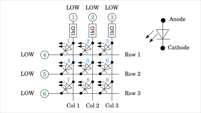
Figure 1:
Here you can see a matrix of 9 LEDs. The three columns are connected to GPIOs 1, 2, and 3 via a 1kΩ resistor, the rows directly to GPIOs 4, 5, and There is a LOW signal on all GPIOs, with which no voltage can be measured at any point in the matrix - all LEDs are switched off.
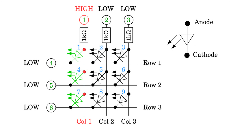
Figure 2:
Now GPIO number 1 is set to HIGH signal, with which LEDs number 1, 4, and 7 are connected in the forward direction and so start to light up.
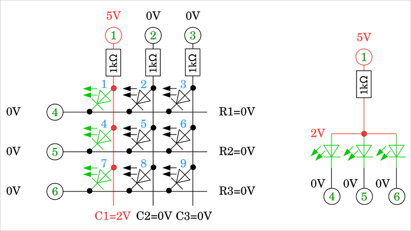
Figure 3:
LOW signal, thus 0V, is on the cathodes (tip of the triangle with the dash at the diode symbol) of the three LEDs, the anodes (blunt side of the triangle) are connected to the HIGH signal, i.e. 5V, at GPIO 1 via the 1kΩ resistor. Consequently, the threshold voltage drops across the LEDs. This voltage depends on the type of LED used and is usually in the range of 1V to 3V. The threshold voltage can be measured at the anodes that are directly connected to one another.
In the following, we assume that the logic level is 5V and the threshold voltage of the LEDs is 2V.
The resistor at GPIO number 1 forms a voltage divider with the three LEDs, polarized in the forward direction. The three LEDs are connected in parallel as can be seen in the equivalent circuit to the right of the matrix.
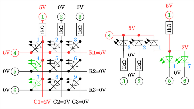
Figure 4:
Now, GPIO number 4 is also set to the HIGH level, which turns LED 1 OFF, while LEDs 4 and 7 remain ON.
The equivalent circuit on the right shows that it is now 5V on the cathode of LED 1 - which is directly connected to GPIO 4 - and 2V on the anode, by what this diode is switched in the reverse direction and no longer lights up. The cathodes of LEDs 2 and 3 are also directly connected to GPIO number 4, which means that 5V is applied here. The anode of LED 2 is connected to GPIO 2 via a series resistor, which also applies to the anode of LED3 and GPIO 3. Both are therefore at 0V level, with which LEDs 2 and 3 are switched in the reverse direction and do not light up.
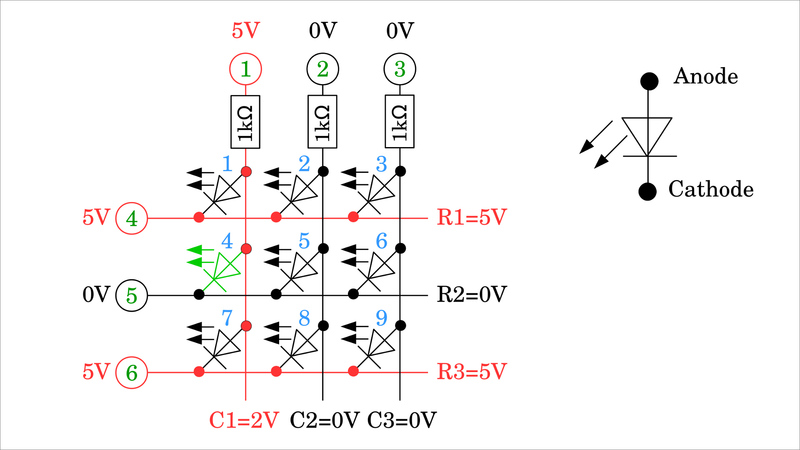
Figure 5:
In order to finally switch off LED 7 and only keep LED 4 ON, GPIO 6 must also be switched to the HIGH level, i.e. 5V.
Figure 6:
The equivalent circuit shows that only LED 4 is polarized in the forward direction. LEDs 5 and 6 are not shown in the equivalent circuit diagram. 0V is present on both the anode and the cathode, which means that no current can flow through them.

Figure 7:
Same as at the beginning, all LEDs are finally switched off when GPIO number 5 is also set to a HIGH signal. This is the better choice for the initial state of an LED matrix because from this all LEDs remain switched off if GPIO number 1, 2, or 3 is now set to HIGH signal.
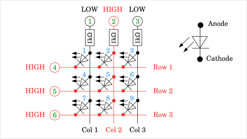
Figure 8:
Here, this is the case for GPIO number 2. The LEDs in column 1 (LED 1, 4, 7) and column 3 (LED 3, 6, 9) are switched in the reverse direction with 5V on the cathodes and 0V on the anodes. The diodes in column 3 (LEDs 2, 5, 8) have 5V applied to both the cathodes and the anodes, which means that no current can flow through any of the 3 LEDs.
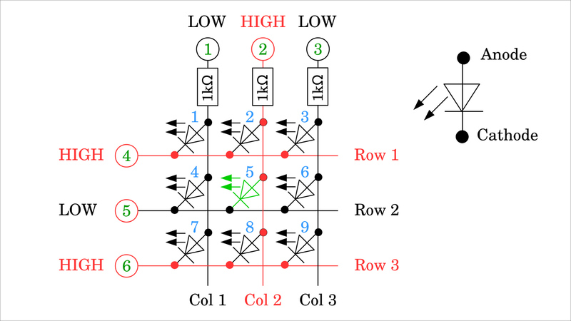
Figure 9:
Not until one of the GPIOs numbers 4, 5, or 6 goes LOW a current flows through the network. Here, GPIO 5 is set to LOW, which means that a current exits GPIO number 2 and flows through the resistor and LED 5 into GPIO number 5. GPIO 2 is the current source, GPIO 5 is the current sink.
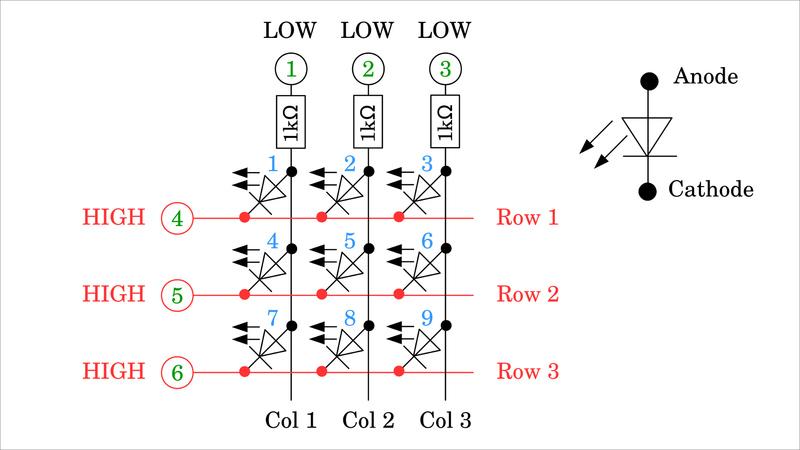
Figure 10:
Before switching on the next LED, the initial state of Figure 7 should be restored.
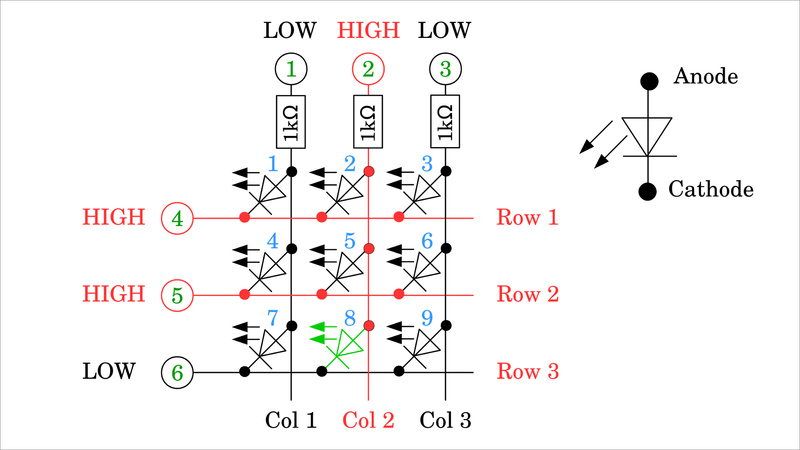
Figure 11:
To switch on any LED, the GPIO of the corresponding column must be set to the HIGH signal, first and the GPIO of the corresponding row must be set to the LOW signal afterward. Here these are column 2 (GPIO 2) and row 3 (GPIO 6), with which LED number 8 is switched on.
Six GPIOs are sufficient to switch 9 LEDs individually.

Figure 12:
However, the LEDs cannot be switched independently:
In Figures 2, 4, and 5 it can be seen that the LEDs of a column can either be switched on individually, in groups of two, or all three at once, for which column 1 must be set to HIGH signal and the respective row(s) to LOW.
It works similarly when a row is switched to LOW. Depending on which column(s) are on the HIGH signal, the corresponding LEDs light up. Here, this is the case for LEDs 8 and 9.
Figure 13:
However, it is not possible, e.g. to only switch on the two LEDs number 3 and 8:
For LED number 3, row 1 (GPIO 4) must be set to LOW and column 3 (GPIO 3) to HIGH. For LED number 8, row 3 (GPIO 6) must be set to LOW and column 2 (GPIO 2) to HIGH. This inevitably also turns on the two LEDs 2 and 9.
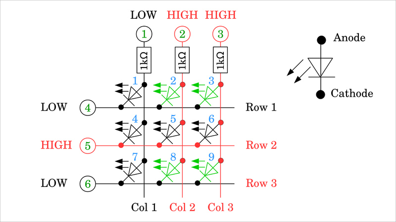
Figure 14:
The LED matrix can be expanded as required. In a matrix of 4 columns and 4 rows, 8 GPIOs are needed to control 16 LEDs. For square matrices, we get 25 LEDs with 10 GPIOs, 36 LEDs with 12 GPIOs, 42 LEDs with 14 LEDs, and so on.
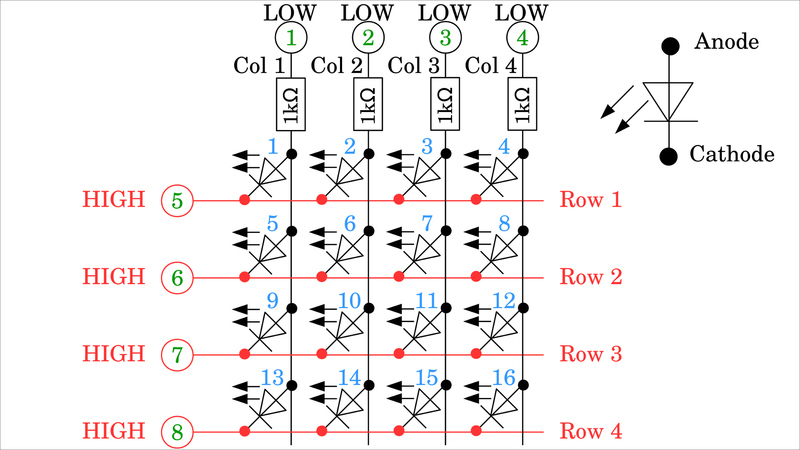
Figure 15:
Unsymmetrical matrices are also possibly composed of e.g. 3 rows and 4 columns, which results in 12 LEDs with 7 GPIOs needed. The ratio of LEDs to GPIOs is the most favorable for square matrices.
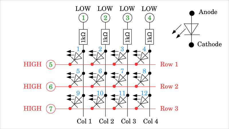
Figure 16:
Up to now, I have drawn the matrices in Common Row Cathode configuration. The cathodes of the LEDs in each row are directly connected to each other. In the drawing shown here, it is a common row anode configuration, accordingly, the LEDs in each row are connected on their anode side. In order to address an LED in this arrangement, a HIGH signal may only be present on the corresponding line, while the remaining lines are set to the LOW signal. All columns except the column of the LED to be switched on must be set to the HIGH signal. The signals are inverted compared to the Common Row Cathode configuration.
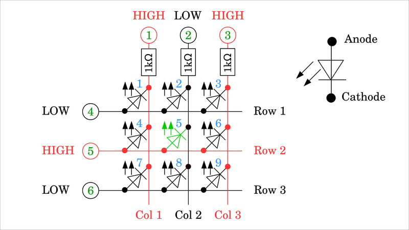
Figure 17:
When calculating the resistance values needed, the maximum current of the GPIOs must be kept in mind! For the Arduino Uno, these are e.g. 20mA per GPIO. According to Ohm's law, with a logic voltage of 5V we get:
R = U / I = 5V / 0.02A = 250Ω
Since there is also a drop in voltage across the LED, this forward voltage can be subtracted from the logic voltage. However, for safety reasons, I am using a higher value in the following. Note, that all LEDs in a row can be switched on simultaneously in the matrix, which means that a significantly higher current flows in parts of the network! The GPIOs of a column are connected to the LEDs via series resistors. Thus, the source current per column is definitely less than the maximum value. However, the rows are directly connected to the LEDs. If all the LEDs in a row are switched on at the same time, the sink current will add up to a value well above the maximum! To prevent this, the resistance values must be adjusted. The maximum current per GPIO is divided by the number of columns so that you get for a 3x3 matrix:
R = N * U / I = 3 * 5V / 0.02A = 750Ω
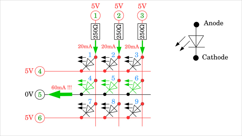
Figure 18:
Plan "B" consists of connecting the rows to the LEDs via series resistors, too. With that, the lower resistance value of the previous calculation is sufficient and this does not have to be adjusted if the LED matrix is expanded. If the maximum brightness of the LEDs is needed, the signals of the GPIOs must be amplified e.g. by transistors, as can be read in the following chapters.
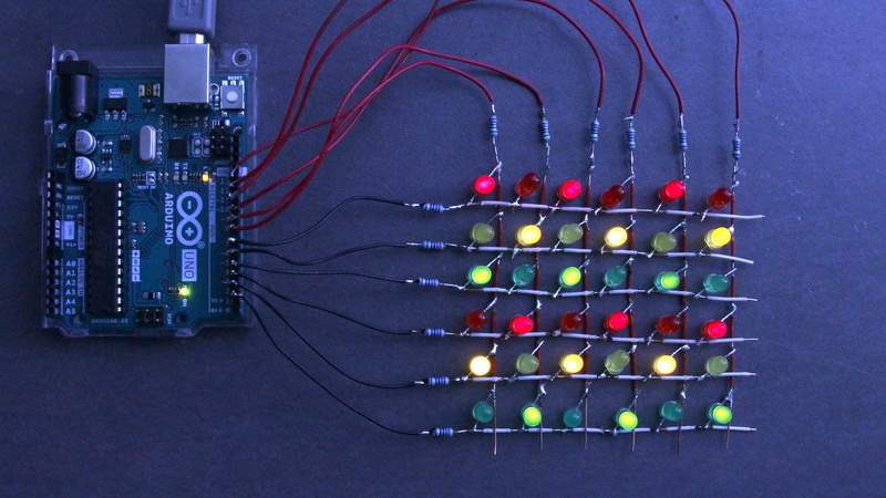
Figure 19:
You can take advantage of the sluggishness of the human eye to give the impression that you can switch any combination of LEDs. As shown, the LEDs in each row can be controlled in any combination. The trick now is to drive the rows at a very high frequency from top to bottom and only switch on the desired LEDs. The active row is - based on a common row cathode configuration - switched to the LOW signal, the columns of the LEDs to be activated are on the HIGH signal. In order to build up the desired illusion, the matrix must be switched at a frequency of more than about 25Hz. With a 3x3 LED matrix, this means that a single row is active for only about:
1s / (25 * 3) ≈ 13ms
before the next line is activated.
In the photo, it looks as if every second LED is permanently switched ON, which would not be possible without multiplexing. In truth, each line is only activated for about 1ms.
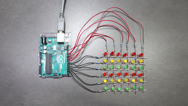
Figure 20:
6x6 LED matrix with different colored LEDs:
12x 5mm LED Yellow
12x 5mm LED Green
12x 5mm LED Red
12resistors, 270Ω each
I soldered the LED matrix here as a wire mesh to get it close to the circuit diagram. Make sure that no bare wires touch each other at the grid points! I put on small pieces of the insulation, which is quite fiddly. The circuit is easier to solder on a prototype board.
You can get a software example for Arduinos demonstrating multiplexing as Download.
NextPCB is A Real PCB Manufacturer that can Also, Sourcing parts
If you know more parts that are good for building circuits shown on this page, please leave a comment.
Many thanks to Norbert, wrote this...if you wanna know more check out:
https://homofaciens.de/
Still, need help? Contact Us: support@nextpcb.com
Need a PCB or PCBA quote? Quote now


 Printed Circuit Boards
 Surface


dref
I will do a led matrix according to your page.