
 NextPCB Capabilities
Printed Circuit Boards
NextPCB Capabilities
Printed Circuit Boards
 PCB Assembly
 Layer Buildup
 SMD-Stencils
 PCB Design-Aid & Layout
 Mechanics
 Quality
 Drills & Throughplating
 Factory & Certificate
 PCB Assembly Factory Show
Certificate
PCB Assembly Factory Show
Certificate
Support Team
Feedback:
support@nextpcb.com


Relays are one of the most crucial components to protect and switch control circuits and components. The relay operates based on the provided voltage and current that make or break the contact connection or the circuits. Since there has been a significant increase in technologies and electronic devices, relays have become the need of every board. These are thus called PCB relays.
You can select the PCB relay board based on your project requirement since there are various types of PCBs according to your need and requirements. This article will briefly explain PCB relays, some preliminary design considerations while designing PCB relays, and all the relay types used in circuit boards.
In this article,
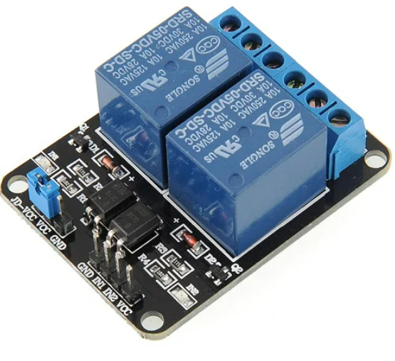
PCB relay is one of the smallest relays that can be mounted directly to a PCB. The size and weight of these relays make them suitable for mounting as through-hole components on a board. Relays are used to control low-power circuits with high-voltage circuits. One of the best advantages of this PCB relay is the galvanic isolation that is not in the transistor-based switching.
The working of PCB relays is similar to that of regular relay types. The size of the relays makes them relatively compact to fit in the PCB. The high voltage rating relays are attached to the board with the help of the through-hole process. PCB relay boards have a wide range of relay types; thus, the user can select these PCB relays based on their project requirements.
Some of the features of the PCB relays are as follows:
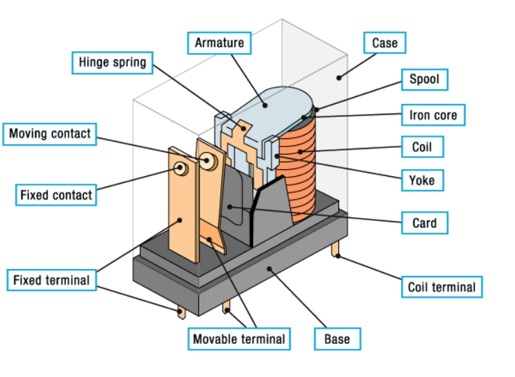
A relay is nothing but an electromagnetic switch. The crucial part is the electromagnetic coil. When current passes through it, it turns into a temperature magnet. This magnetic field operates through the metal plate that connects to the armature, changing the contact point position. Thus, the magnetic field activates the armature and makes or breaks the connection with the contact point. This creates switching as the field can open or close the contacts. This is the basic working of the relay.
Usually, a PCB relay's design starts with removing the relay's plastic case. This visualizes all the relay parts, including coil and contact, spring, yoke, and armature. The proper selection of relays and the seamless mounting process determine the appropriate functioning of the PCB relay circuit.
Therefore, some contacts in the relay are closed, and others are opened. The number of contacts in other relays may vary depending on their utility. The yoke is also connected to the armature with a wire, ensuring continuity between the circuit track and armature against the PCB's moving contacts through the yoke. Relays are soldered to PCBs.
The table below shows a standardized method to identify electromagnetic relay terminals.
| Terminal | Terminal Description |
|---|---|
| _COIL | voltage connects to the terminal to supply power to the coil |
| COIL | voltage connects to the terminal to supply power to the coil |
| NO - Normally Open | Connects to a device that the relay will power when the coil receives sufficient voltage to energize. The device switched off when the relay has no power and switches on when the relay receives power. |
| NC - Normally Closed | The terminal connects to the device to power when the relay receives no power. The device remains on when the relay has no power and switches off when the relay receives power. |
Based on Poles and Throws
It includes the single pole and double throw. The one terminal of the SPDT relay connects one of the two positions that can conduct.
It refers to the single pole and single throw relay. It can control only one circuit as the pole has only one position.
It refers to the double pole and single-throw relay. It consists of two terminals in single isolated circuits working as two of the SPDT relays.
It refers to the single pole double throw relay and it can control one circuit at a time. Most importantly it has two conducting positions. In the two states of SPDT relays, one remains closed while the other remains open, and vice versa.
Electromagnetic relays are a combination of electrical and mechanical components. When the relay is triggered or activated, they work in the combine and thus move the mechanical contact. So, the primary thing about this kind of relay is the electromagnet that helps to generate the electromagnetic field. This field opens or breaks the contact sets. AC and DC can efficiently operate this kind of relay based on their applications, which benefits this relay type. There is just a slight difference between the coil constructions such that the freewheeling diode in the DC coil prevents de-energizing and back EMF.
The use of semiconductors in solid-state relays differs from electromagnetic relays. It works on isolating the low-voltage circuit from the high-voltage circuit with the help of an optocoupler. It works at high speed and gains higher than electromagnetic PCB relays. The higher gain results from the lower energy control concerning the higher power output. The primary benefit of Solid state relays is low power consumption compared to electromagnetic relays. Besides, the life span of these relays is higher as there is no mechanical contact that burns while the relay activates.
On the other hand, the major drawback of SSR relays is the drop of its nominal voltage across the semiconductor. As a result, it wastes power in the form of heat.
The central part of this relay system is the bimetallic strip. In other words, it comprises two metals with various thermal expansion coefficients. When current passes through the conductors, it generates heat. The metals with a higher expansion coefficient expand faster than others. This difference in temperature changes shifts the contact position, activating the trip circuitry. This results in the switching mechanism of the relay.
Since it works with temperature change thus helps to protect the devices from overheating. Therefore, there are mainly used for electric motor protection and temperature sensors.
As per the name, mixed relays combine solid-state relays and electromagnetic relays. It includes both electronics and electromagnetic components in parallel positioning. Further, the two processes, rectification, and the output section get handled by the rectification and electromagnetic section.
Mixed relay overcomes the drawbacks of these two relays, power waste in heat form, and contact arcing problems in SSR and EMR, respectively. Furthermore, the primary benefit of this relay is the use of lower energy compared to solid-state relays, which results in lower power consumption.
The internal mechanism is a crucial part of any relay system for effective working operations. The distortion of this mechanism can distort the whole relay system. Thus, you must be careful with soldering and washing during the mounting process. Usually, the PCB manufacturer recommends:
On the other hand, they provide the standard conductor thickness of 35 μm and 70 μm. But the relays, like electromagnetic and thermal, acts differently while exposed to magnetic and heat fields.
Thus, during the PCB design process, these places should be kept away from semiconductors, heat-generating components, and transformers. Besides, it would help if you focused on mounting the relays for the vibrations and shock to apply perpendicularly to the relay armature direction.
A mounting, flux, and pre-heating application follow the soldering process. The process is both manual and automatic. Automatic soldering shares the following methods:
This process is used unless the conditions are specified. Otherwise, based on the relay types, various temperature is applied. In the case of multi-layer PCB, the performance of the relay could degrade because of the higher thermal capacity.
In an unenergized state or relay, NO and NC remain open and closed, respectively. The testing of the relay requires a multimeter. After then, you can look for the following steps to test the PCB relays:
PCB relays work as a protective system for the whole circuit system. Although the relays are smaller, they can function well to save the entire system from damage and works like the standard-sized ones. The PCB design is complete by considering the PCB relay aspects. Thus, it requires special techniques for mounting the relay in the board. Similarly, to check the functionality of the relay, the manufacturer should consider the PCB design requirements.
Still, need help? Contact Us: support@nextpcb.com
Need a PCB or PCBA quote? Quote now


 Surface

