NextPCB Capabilities
Printed Circuit Boards
NextPCB Capabilities
Printed Circuit Boards
 PCB Assembly
 Layer Buildup
 SMD-Stencils
 PCB Design-Aid & Layout
 Mechanics
 Quality
 Drills & Throughplating
 Factory & Certificate
 PCB Assembly Factory Show
Certificate
PCB Assembly Factory Show
Certificate
Support Team
Feedback:
support@nextpcb.com


Introduction
Digital electronics rely on fundamental building blocks called logic gates to perform various operations in computers and electronic circuits. In fact, complex computer circuits are nothing except just a combination of logic gates and timers. XOR (exclusive OR) gates and XNOR (exclusive NOR) gates are two essential logic gates as they play a crucial role in processing binary information.
XOR and XNOR gates find widespread applications in digital logic circuits and information processing systems, particularly in error detection and correction. Both XOR and XNOR gates also contribute significantly to the design and functionality of digital electronics, facilitating operations essential to computer systems, communication protocols, and various electronic devices. In this article, we'll explore the characteristics, truth tables, circuit diagrams, and applications of XOR and XNOR gates.
An XOR gate is a digital logic gate that outputs HIGH (1) only when the number of HIGH inputs is odd. In other words, the output is high when the number of true inputs is not equal. XOR gates are often denoted by the symbol ⊕ or by the acronym XOR.
Another way of looking at the operation of the XOR gate is that it acts like a binary addition of the inputs. In binary addition, 1 + 1 = 10. In the case of XOR where both inputs are 1, the answer is 0 as the 2^1 digit is dropped.
The truth table of an XOR gate illustrates its behavior for all possible input combinations. For a two-input XOR gate, the output is HIGH when the inputs are different and LOW when they are the same.
A B A ⊕ B
0 0 0
0 1 1
1 0 1
1 1 0
As you can see above when input A is LOW and input B is LOW, the output is LOW. Similarly, when input A is HIGH and input B is HIGH, the output is also LOW. Only when input A is HIGH and input B is LOW or when input A is LOW and input B is HIGH that the output becomes HIGH.
Free Components Worldwide Shipping
The XOR gate circuit is constructed using transistors and other electronic components. It produces the specified output based on the XOR truth table. The circuit diagram typically consists of input terminals, logic gates, and an output terminal.
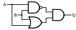
The XOR gate can be created by using a special combination of a NAND gate, an AND gate, and an OR gate. The circuit diagram is shown below:
When both inputs A and B are HIGH, the AND gate is LOW and the OR gate is HIGH. Because their outputs are the inputs to the AND gate, that means the output at Q is HIGH. Alternatively, when A is HIGH and B is LOW, the NAND gate and the OR gate are HIGH. This means the output Q is HIGH.
An XOR gate can also be created using NAND gates or NOR gates only. Here’s how:
XOR Gate using NAND Gates:
XOR Gate using NOR Gates:
Both constructions involve chaining multiple NAND or NOR gates to mimic the behavior of an XOR gate. In practical applications, XOR gates are often available as standard components.
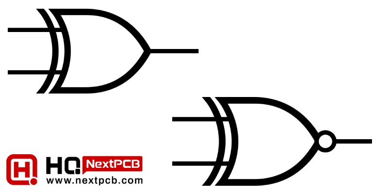
The logical symbol for an XOR gate is often represented by the ⊕ symbol. This symbol is universally recognized in digital circuit diagrams and schematics, making it easy to identify XOR gates in complex electronic systems.
While the basic XOR gate has two inputs, multiple-input XOR gates can also exist. These gates produce an output based on the parity of the true inputs, making them versatile for various applications.
A 3-input XOR gate extends the XOR functionality to three binary inputs. The output is true only when an odd number of inputs are true, following a similar principle as the 2-input XOR gate.
A B C Output
0 0 0 0
0 0 1 1
0 1 0 1
0 1 1 0
1 0 0 1
1 0 1 0
1 1 0 0
1 1 1 1
In the XOR gate, the output is 1 (True) when an odd number of inputs are 1, and 0 (False) otherwise.
An XNOR gate is another digital logic gate that outputs true (1) only when the number of true inputs is even. In other words, the output is high when the number of true inputs is equal. The XNOR gate is also known as an equivalence gate and is denoted by the symbol ⊙ or by the acronym XNOR.
Another way of looking at the operation of the XNOR gate is that it is the negative result of the binary addition of the inputs. In the case of XNOR where both inputs are 1, the answer is 1 as it is the opposite of the XOR result which is 0.
The truth table for a two-input XNOR gate reveals that the output is true when both inputs are the same and false when they differ.
A B A ⊙ B
0 0 1
0 1 0
1 0 0
1 1 1
The XNOR gate is the inverse of the XOR gate. When input A is LOW and input B is LOW, the output is HIGH. Similarly, when both inputs are HIGH, the output is also HIGH. Only when both inputs are LOW or both inputs are HIGH that the output becomes HIGH.
Similar to the XOR gate, the XNOR gate is implemented using electronic components to create a circuit that follows the XNOR truth table. The circuit consists of input terminals, logic gates, and an output terminal.
The XNOR gate can be created using a special combination of AND, OR, and NOT gates. Let's denote the inputs as A and B. The AND gate in the circuit above ensures that the output is only high when the inputs are high. This accounts for the cases where an even number of inputs are high. The NOT gate is used to invert the inputs. The OR gate in the diagram checks for the cases where all two inputs are low (inverted from high). This combination is shown below:
So, if either all inputs are high or all inputs are low, the XNOR gate produces a high output; otherwise, it produces a low output. This logic configuration ensures that the XNOR gate behaves according to its definition.
The XNOR gate can also be created using NAND gates only or NOR gates only. Here’s how:
XNOR Gate using NAND Gates:
XNOR Gate using NOR Gates:
In both cases, these constructions demonstrate how XNOR gates can be created using either NAND gates or NOR gates. Keep in mind that practical applications often use dedicated XNOR gate components when needed.
Extending the XNOR gate to three inputs, a 3-input XNOR gate operates based on the parity of the true inputs, producing an output that is true only when the number of true inputs is even.
A B C Output
0 0 0 1
0 0 1 0
0 1 0 0
0 1 1 1
1 0 0 0
1 0 1 1
1 1 0 1
1 1 1 0
In the XNOR gate, the output is 1 (True) when an even number of inputs are 1, and 0 (False) otherwise.
XOR gates find applications in various digital systems, including error detection and correction, arithmetic operations, and cryptographic algorithms. They are fundamental in building flip-flops, adders, and other essential components of digital circuits.
Perhaps the most common use of XOR gates is parity checking, a method of error detection and correction. Parity checking is a method used in digital communication and data storage to detect errors in transmitted or stored data. It involves the addition of a parity bit to the data, and the type of parity used (even or odd) depends on the specific application. An XOR gate is commonly used in parity checking, particularly in odd parity checking.
Let's consider odd parity checking as an example. In odd parity, the goal is to ensure that the total number of '1' bits in the data, including the parity bit, is odd. Here's how an XOR gate is utilized in the process:
Data Transmission:
Assume you have a stream of data bits that you want to transmit.
The XOR gate is used to calculate the parity bit. This is often done by XORing all the data bits together.
The result of this XOR operation is the parity bit.
Transmission with Parity:
The parity bit is appended to the original data.
The complete set of transmitted bits (data + parity) is sent to the receiver.
Reception and Checking:
At the receiving end, the received data (including the parity bit) is passed through another XOR gate.
The XOR gate is used to calculate the received parity bit using the received data bits.
Error Detection:
If the received parity bit is the same as the calculated parity bit, it indicates that there are an even number of '1' bits in the received data, and the data is considered error-free.
If the received parity bit differs from the calculated parity bit, it suggests that there is an error in the transmitted data.
In summary, the XOR gate is crucial in parity checking for its ability to detect discrepancies between the calculated and received parity bits. If the XOR result is 0, the parity is even (no error), and if the XOR result is 1, it signals an odd parity (error detected).
XNOR gates can be also used in parity checking. The primary difference lies in how even and odd parity is determined. XOR gates produce even parity when the result is 0, while XNOR gates produce even parity when the result is 1. The choice between XOR and XNOR parity checking depends on the specific requirements of the application and the desired parity type (even or odd).
In the realm of digital electronics, XOR gates, and XNOR gates are fundamental building blocks that play crucial roles in processing binary information. Understanding their truth tables, circuit diagrams, and logical symbols is essential for designing and analyzing digital circuits. With their versatile applications, XOR and XNOR gates continue to be integral components in the world of digital technology.
- How To Read Electrical Schematics
- The Ultimate PCB Routing Guidelines
- Free Worldwide Shipping on Over 600,000 Electronics Components with HQ Online
- Free PCB Assembly Offer is Now Live: Experience Reliable PCB Assembly from HQ NextPCB
- HQ NextPCB Introduces New PCB Gerber Viewer: HQDFM Online Lite Edition
Still, need help? Contact Us: support@nextpcb.com
Need a PCB or PCBA quote? Quote now


 Surface