NextPCB Capabilities
Printed Circuit Boards
NextPCB Capabilities
Printed Circuit Boards
 PCB Assembly
 Layer Buildup
 SMD-Stencils
 PCB Design-Aid & Layout
 Mechanics
 Quality
 Drills & Throughplating
 Factory & Certificate
 PCB Assembly Factory Show
Certificate
PCB Assembly Factory Show
Certificate
Support Team
Feedback:
support@nextpcb.com


Introduction
Electrical schematics are the common language of technicians, engineers, and enthusiasts because they convey complex circuits and systems in a pictorial format. The secret to solving the riddles hidden in these complex schematics is this extensive tutorial, "How To Read Electrical Schematics." or reading electrical schematics.
From power sources to switches, and from resistors to integrated circuits, & how to read wiring schematics or how to read wiring diagrams, we will cover it all. You will gain a thorough understanding of electrical schematics, what is an electrical schematic & how electrical and electronic systems operate as you go through this text, be able to troubleshoot problems, and even design your own circuits.
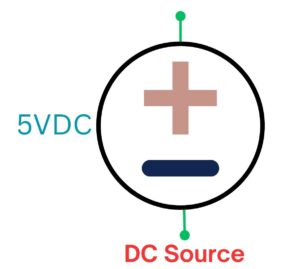
Power sources are the lifeblood of electrical and electronic systems, providing the energy necessary to drive circuits and devices. To read and comprehend these electrical schematic diagram, you must understand the different types of power sources and their representation in electrical schematics.
Direct current (DC) power sources are a common starting point in electrical schematics. These sources provide a steady flow of electrical energy in one direction. In schematics, a straight line with a plus (+) and minus (-) sign typically represents DC power sources, denoting the positive and negative terminals, respectively.
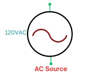
Alternating current (AC) power sources are essential for many devices. They provide electricity that alternates in polarity, typically at a specific frequency, such as 60 Hz. Look at the circuit diagram what does the diagrams show:
In electrical schematic symbols, a sine wave symbol represents AC power sources to depict the alternating nature of the current.
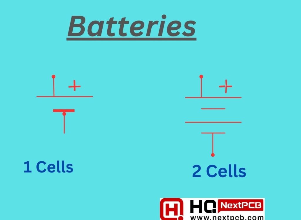
Batteries are portable DC power sources used in countless electronic devices. Their schematic representation includes the standard DC power source symbol, indicating the positive and negative terminals, with the voltage level specified.
A battery is an electrochemical device that converts chemical energy into electrical energy. While technically, a battery comprises two or more galvanic cells, it's commonly used to refer to a single cell. Each cell has a positive cathode and a negative anode separated by an electrolyte that permits ion movement. Engineers configure these components to generate sufficient voltage and current for powering devices.
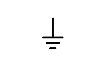
Ground is a fundamental and crucial concept in circuit design, usually symbolized as a horizontal line with three downward-pointing lines. Ground is the common return path of a circuit, where current returns to its source. This is often referred to as the negative side in a circuit.
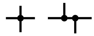
Terminals, which act as connecting points and are represented as labeled circles or squares, are essential components of electronic systems. They create connections between wires, parts, or gadgets to allow current or signal flow. They are uniquely identified by designating certain connections.
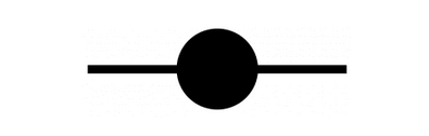
Terminal connections are different from nodes or junctions which have solid circles:
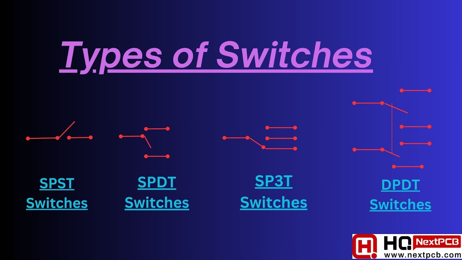
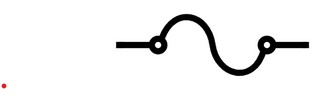
Switches help in controlling electronic systems, from turning on lights in your home to enabling advanced functions in complex electronic devices. They are represented by various symbols that denote their specific type. These symbols often include lines and shapes that indicate the switch schematics action and configuration.
SPST Switches (Single-Pole, Single-Throw): These are simple, on-off switches, represented in electronic schematics with a single break in the line to show the normally open switch symbol or closed state.
SPDT Switches (Single-Pole, Double-Throw): SPDT switches have three terminals and can be used to connect one input to either of two outputs. They are symbolized by a center-off position in schematics.
SP3T Switches are devices that are used to route signals to one or more signal paths.
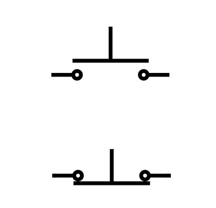
Momentary switches are only open or closed while they are pressed. The most popular sort of momentary switch is the push button switch. These switches operate in one of two modes: generally open or normally closed. The top schematic symbol below depicts an open normally open push button switch, whereas the bottom symbol depicts a closed typically closed push button switch:
Multi-point switches allow you to control the flow of an input current to multiple different output paths.
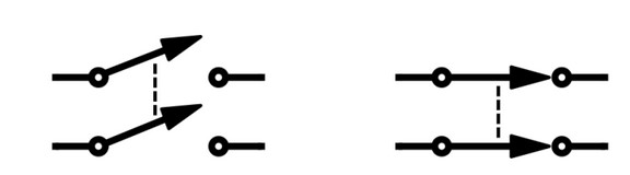
DPST (double pole, single throw) switches have two inputs and two outputs and allow you to control the flow of an input current to two different output paths. Because the switches are single throw, the two output terminals will both be switched on and off at the same time. The schematic symbols below show an open DPST switch (left), and a closed DPST switch (right):
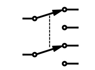
DPDT (double pole, double throw) switches have two terminals for input current and four terminals for output current. These switches allow you to change the path of two input currents to four separate output paths. A DPDT switch is represented schematically as follows:
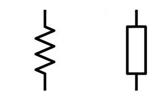
Resistors are typically represented by a simple zigzag or rectangular symbol. The symbol doesn't change with the resistor's resistance value; instead, a numerical label often indicates the resistance in ohms (Ω) near the symbol.
Here are some common functions of Resistors:
1. Current Limiting: Resistors are commonly used to limit the amount of current flowing through a circuit, or how to read circuit diagrams for protecting components and ensuring safe operation.
2. Voltage Division: They help divide voltage levels within a circuit, allowing for precise control of voltage at specific points.
3. Signal Conditioning: Resistors are essential in signal processing and filtering, affecting the amplitude and frequency response of signals.
4. Biasing: They play a role in setting the operating point of transistors and other active components.
The symbol on the left represents the US convention, while the symbol on the right represents the international standard:
You may also like - What Are 10k Resistors and Their Advantages?
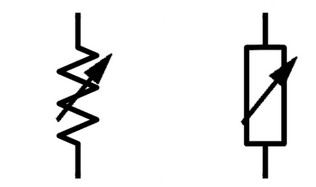
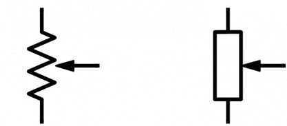
Variable resistors, also known as potentiometers, are indispensable components in electrical and electronic systems, offering a means to adjust and control resistance within a circuit.
A distinctive zigzag line with an arrow denoting the wiper, the movable component enabling resistance adjustment, symbolizes them. Schematics often do not specify their resistance value, but they may label them as potentiometers.
In electronics, potentiometers, also referred to as "pots," are flexible variable resistors. They enable continuous and accurate resistance control for functions such as brightness or sensor sensitivity adjustment. Accurate resistance adjustments in basic electrical wiring diagram or electrical systems are ensured by familiarity with potentiometer symbols in schematics.
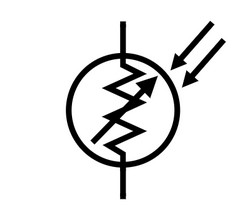
Photoresistors, also known as light-dependent resistors (LDRs) or photocells, are fascinating components that are highly responsive to changes in light intensity. Unlike fixed resistors, photoresistors don't have a static resistance value but instead exhibit variations based on the incident light intensity.
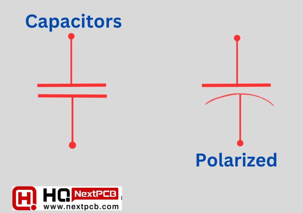
Capacitors play a crucial role as passive electronic components in various applications, spanning from energy storage to signal filtering and timing. The basic capacitor symbol consists of two parallel lines, representing the plates, with a curved line between them, symbolizing the dielectric material that separates the plates. Capacitor symbols can vary to indicate specific types, such as polarized, non-polarized, and variable capacitors.
Capacitors serve several important functions in electronics:
1. Energy Storage: They store electrical energy and release it when needed, which is vital in applications like power supply filtering.
2. Signal Coupling: Capacitors allow AC (alternating current) signals to pass while blocking DC (direct current) signals, making them useful for coupling and decoupling circuits.
3. Timing and Oscillation: Capacitors are key components in timing circuits, like RC oscillators, where they set the oscillation frequency.
4. Filtering: They smooth out voltage variations and filter unwanted noise in power supplies and audio circuits.
Non-polarized capacitors are versatile electronic components that can store and release electrical energy in both directions without a fixed polarity. These capacitors are widely used in electronics for various applications.
They are represented with the standard capacitor symbol – two parallel lines representing the plates, separated by a curved line indicating the dielectric material. Unlike polarized capacitors, non-polarized capacitors have no polarity markings, as you can connect them in either direction.
Polarized capacitors find use in circuits where voltage direction is crucial. They store and release electrical energy while maintaining specific polarity.
Electrolytic capacitors, a common type of polarized capacitor, depict a curved line, indicating the electrolyte, and a plus (+) sign near the positive terminal. The negative terminal typically lacks a negative (-) sign but is identifiable as the negative terminal by its shorter lead on the physical component.
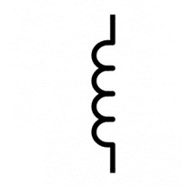
Inductors are vital passive components in the world of electronics, offering unique properties that enable the storage of energy in magnetic fields. These components are integral to a wide range of applications, from filtering signals to controlling currents and creating oscillators. They are represented using a coil symbol.
The coil symbol consists of a series of loops, indicating the coil's wire winding, and may include a label to specify its inductance value in henrys (H). Additionally, inductors may include arrows to represent the direction of current flow through the coil.
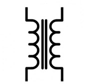
Transformers transfer electrical energy between two or more coils through magnetic induction. They are essentially voltage control devices and are a crucial part of the distribution and transmission of alternating current power. Michael Faraday first proposed the idea of transformers in 1831, and other eminent scientists went on to expand on it.
In electric schematics, transformers typically feature a symbol comprising two coils with a core in the middle. The number of turns on each coil may be specified in the schematic, indicating the turns ratio and helping to determine the voltage transformation.
You may also like - Types of Transformers and their applications
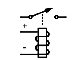
A relay can be described as a basic electromechanical switch. Relays connects or disconnects two circuits in the same way as standard manual switches, which enable us to manually complete or stop an electrical circuit. Relays, on the other hand, work differently from manual switches in that they rely on an electrical signal to trigger an electromagnet, which then connects or disconnects another circuit.
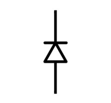
In circuits, diodes have two functions: they convert alternating current (AC) to direct current (DC) and protect against high voltage. Manufacturers use semiconductors like silicon and germanium in the production of diodes to fully exploit their potential. Different diode types have different transmission qualities, which makes them useful for different applications even though they have a one-way current flow.
We have a question that how to learn schematics or learning electrical schematics effectively, it's important to understand that different diode types have varying transmission qualities, making them useful for different applications, despite their one-way current flow.
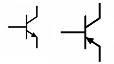
The workhorses of contemporary electronics are transistors, which are essential and adaptable semiconductors used in signal processing, amplification, and switching. Usually, the symbols used to denote transistors match to their type. NPN and PNP for bipolar junction transistors (BJTs) and a variety of symbols for field-effect transistors (FETs) are examples of common transistor symbols. These symbols represent the polarity and mode of operation of the transistor.
Transistors are at the heart of almost every electronic device, from radios and computers to smartphones and televisions. Their ability to control and amplify electrical signals is fundamental for modern electronics.
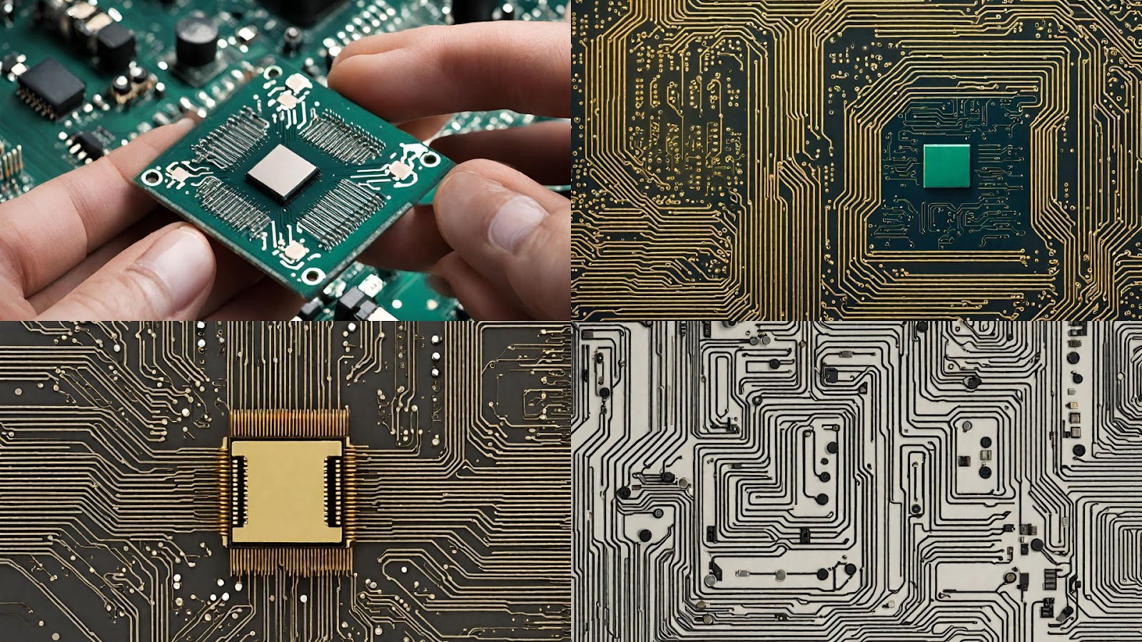
Integrated circuits (ICs), often referred to as microchips or simply chips, are the backbone of modern electronics. They are miniature electronic devices that contain complex networks of interconnected electronic components, such as transistors, resistors, and capacitors, all etched onto a single semiconductor substrate.
Integrated circuit diagram are represented by a rectangular shape with pins or leads extending from the sides. The symbol may incorporate a label or part number indicating the specific IC being used
Integrated circuits have revolutionized electronics, enabling the creation of compact and efficient devices. Their application spans across virtually every facet of modern life, from the smallest gadgets to complex supercomputers.
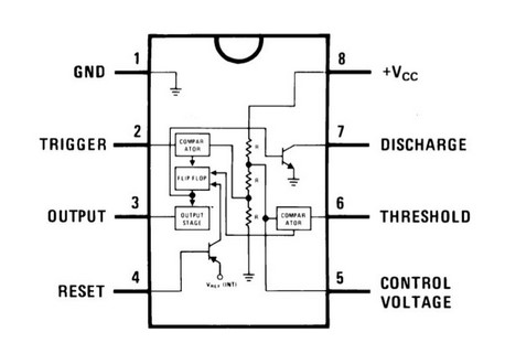
The 555 timer is an iconic integrated circuit (IC) in the world of electronics, celebrated for its versatility and ease of use. Designed by Hans R. Camenzind in 1972, the 555 timer IC has found its way into countless electronic projects, serving as a timing, pulse generation, and oscillator component.
The 555 timer can function in multiple modes, including astable, monostable, and bistable configurations:
The diagram below shows the actual pin arrangement of the 555 timer with the internal schematic diagram of the IC:
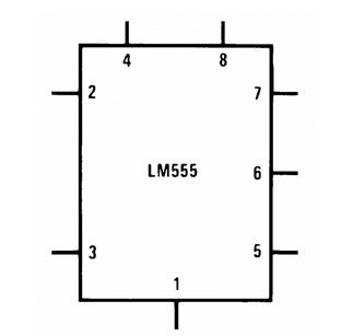
This image is the schematic symbol of the 555 timer used in diagrams:
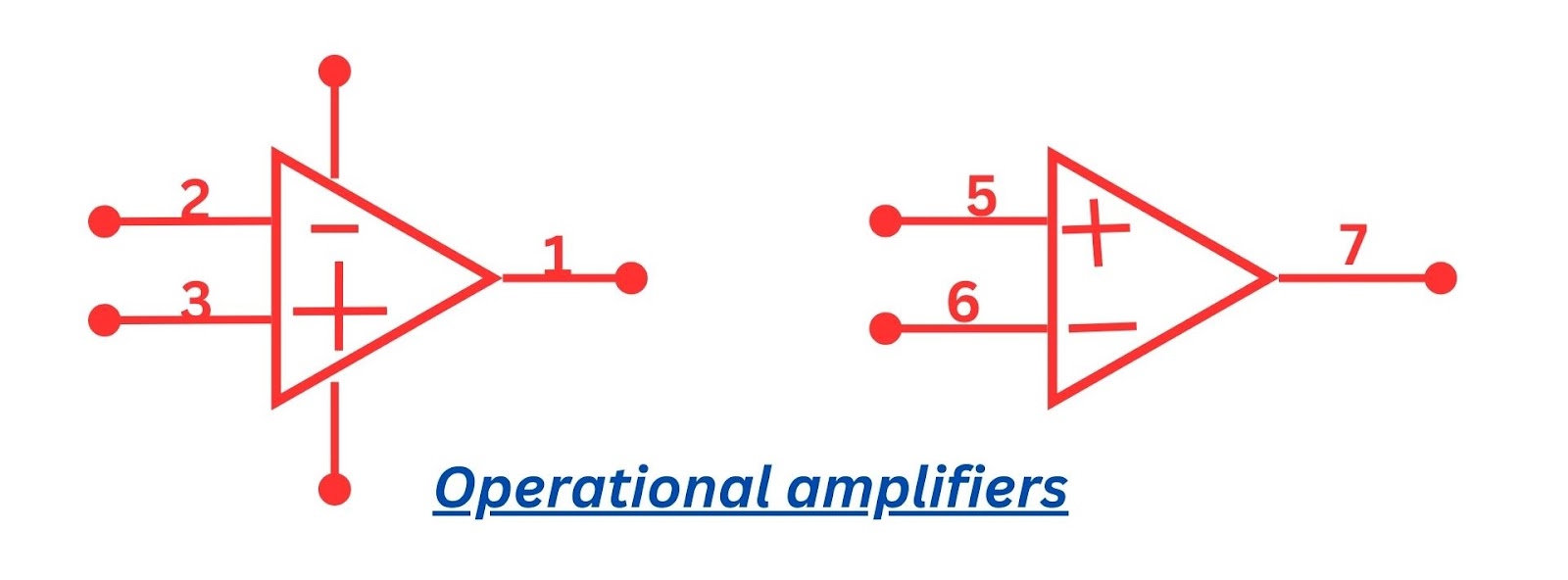
Operational amplifiers, often referred to as op-amps, are common integrated circuits in electronics. Engineers and designers use these versatile devices to amplify, filter, and process electrical signals. Operational amplifiers have a distinctive symbol—a triangle with two input terminals and one output terminal. The plus (+) and minus (-) signs indicate the inverting and non-inverting inputs, respectively.
Operational amplifiers can operate in various modes, including inverting, non-inverting, and differential amplifier configurations. They are the building blocks of analog electronics, finding applications in everything from audio amplification and control systems to sensors and instrumentation.
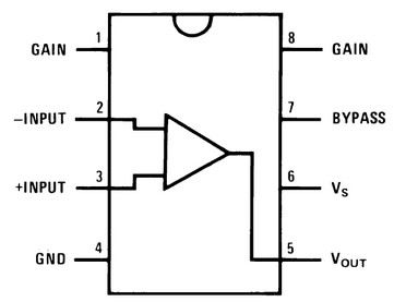
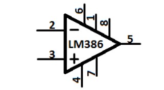
The LM386, an integrated circuit (IC), is a prevalent choice for low-power audio amplification, leaving a substantial mark on the electronics field. It was created by National Semiconductor (now part of Texas Instruments) and is renowned for its straightforwardness, efficiency, and capacity to amplify audio signals in an economical and space-efficient manner.
In electrical schematics reading circuit diagrams, the LM386 appears as a small rectangular box with pins for connections. It is a versatile audio amplifier IC, capable of operating in both low and high-gain modes, making it suitable for a wide range of audio amplification tasks.
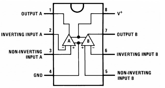
A pin diagram of the LM386:
this is the symbol used in schematic diagrams:
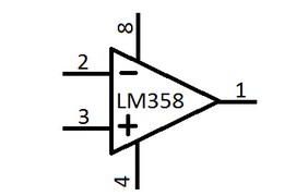
The LM358 is a popular dual-operational amplifier integrated circuit (IC) known for its versatility and reliability in various electronic applications. Texas Instruments (formerly National Semiconductor) developed the LM358, and it finds wide use in tasks that require analog signal processing, amplification, and voltage comparisons.
A rectangular box with pins for connections visually represents the LM358, signifying its dual-op-amp setup. It gains recognition for its distinctive dual-amplifier architecture, housing two individual operational amplifiers in a single IC package.
a pin diagram of the LM358:
here is the symbol used in schematic diagrams:
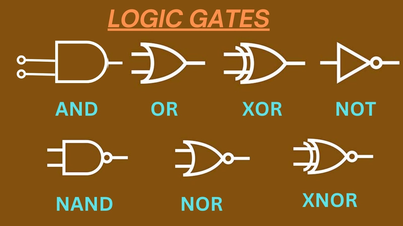
In electrical schematics, logic gates are typically using standardized symbols, each signifying a specific logical operation. Common logic gate symbols include AND, OR, NOT, XOR, NAND, NOR, and XNOR gates. These symbols reflect the fundamental binary operations they perform.
Logic gates are the fundamental elements that enable digital systems to process, store, and transmit information. Their application spans across various digital technologies, from microprocessors and memory units to digital displays and control systems.
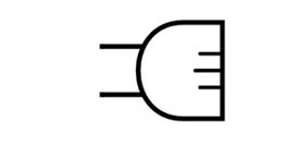
The AND gate is a fundamental digital logic gate that operates on two binary inputs, producing an output of "1" only when both inputs are "1." Its symbolic representation in electrical schematics typically features the word "AND" or an ampersand (&) inside a rectangular shape. The AND gate enforces a logical condition where both inputs must be true for the output to be true.
The OR gate is a fundamental digital logic gate that processes two binary inputs and produces an output of "1" when at least one input is "1." Its standard symbolic representation in electrical schematics typically includes the word "OR" or a plus sign (+) enclosed in a rectangular shape. The OR gate implements a logical condition where the output is true if either or both of its input signals are true.
The NOT gate, also known as an inverter, is a fundamental digital logic gate. It reverses a binary input (1 to 0, 0 to 1) and is symbolized by a triangle in electrical schematics. This inversion forms the foundation of digital logic, transforming binary signals.
The XOR gate, short for "exclusive OR," is a fundamental digital logic gate processing two binary inputs. It outputs "1" for an odd number of "1"s, symbolized distinctly in electrical schematics. It checks for odd or even "1" inputs, producing "1" for odd and "0" for even.
The NAND gate, short for "NOT-AND" gate, is a fundamental digital logic gate that processes two binary inputs. It produces an output of "0" only when both inputs are "1"; otherwise, it outputs "1." In electrical schematics, the NAND gate typically features a distinctive symbol that combines the symbols for the AND gate and the NOT gate.
The NOR gate, also known as the "NOT-OR" gate, is a fundamental digital logic gate that processes two binary inputs. It outputs "1" only when both inputs are "0"; otherwise, it outputs "0." Electrical schematics typically represent the NOR gate with a symbol that combines the symbols for the OR gate and the NOT gate.
The XNOR gate, short for "exclusive NOR" gate, is a fundamental digital logic gate that processes two binary inputs. It produces an output of "1" if both inputs are the same (either both "1" or both "0"). In electrical schematics, the XNOR gate typically features a distinctive symbol that combines the symbols for the XOR gate and the NOT gate.
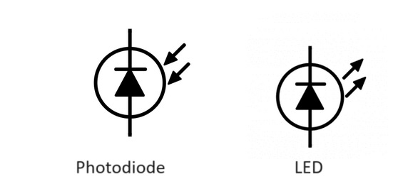
Optoelectronic devices are a class of electronic components that can both detect and emit light, serving as a bridge between the worlds of electronics and optics. These devices play a significant role in a wide range of applications, from communications and sensing to displays and data storage. Understanding how to read an electrical schematic or how to read schematics is essential for comprehending the intricate world of electronics.
Electrical schematics use unique symbols for various optoelectronic devices. These include LEDs, photodiodes, phototransistors, and optocouplers, each with symbols reflecting their specific functions. These devices play a crucial role in modern technology, facilitating communication, sensing, and data storage by merging light and electrical signals. If you're new to reading electrical schematics or reading electrical drawings. It's important to familiarize yourself with these symbols and their meanings. To navigate the intricate how to read a circuit diagram effectively.
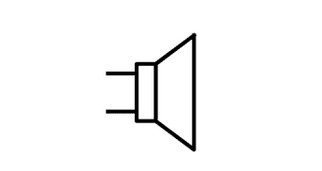
Speakers convert electricity to sound, crucial in audio systems. Varying in size and type, schematics represent them as symbols. From smartphone speakers to concert sound systems, they're essential for audio schematic symbols, using electromagnetism and mechanics to produce sound.
Microphones transform sound into electrical signals, integral in audio systems. Schematics depict them with symbols. They convert acoustic vibrations to electricity, with various types like condenser, dynamic, and ribbon mics. From studio recording to phone calls, they're vital for capturing, transmitting, and processing audio, pivotal in modern tech.
Fuses are vital safety devices in electrical circuits, preventing overcurrent, fires, or equipment damage. Schematics use symbols to indicate their placement. Reading wiring diagrams or how to read a wiring diagram is essential to. Understanding how these fuses are integrated into the overall circuit. Fuses melt or break during excessive current, halting the circuit. They vary in size and type, with specific current ratings. From homes to industries, fuses protect against excessive current flow, ensuring electrical safety.
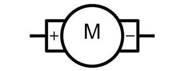
Motors convert electrical energy to mechanical motion, crucial in appliances, vehicles, machinery, and robotics. Schematics use symbols like "M" in a circle to represent them. Motors vary as AC or DC types, each for specific uses. They drive automation, transportation, and manufacturing, powering modern technology for a transformative impact on daily life.
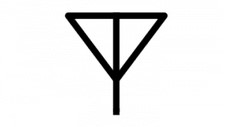
Antennas are vital in wireless communication, transmitting and receiving radio waves. Electronics schematics use symbols reflecting their type, from simple wires to directional antennas. They're pivotal in radio, TV, mobile, Wi-Fi, and satellite communication, tailored to frequency needs. Antenna symbol schematic enable wireless data transfer and connectivity in our interconnected world.
Wires and connections are the unsung heroes of electronic and electrical systems, serving as crucial conduits for electrical current. They lack specific symbols in schematics but are vital. Each line in a schematic represents a wire or connection, and their organization, labeling, and routing are essential for conveying the circuit's design and function.
Key Aspects of Wires and Connections in Schematics:
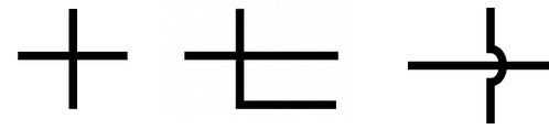
The images below depict the schematic symbols for wires in a circuit when they are physically connected. The dots above the intersections are referred to as nodes:
The absence of a node indicates that the wires are not connected and simply pass by each other, as shown below:
In conclusion, understanding how to read an electrical diagram or wiring schematic is a fundamental skill in the realm of electrical engineering and electronics. Whether you're deciphering electrical blueprints, exploring what electrical schematics symbols signify, or grasping the schematic diagram meaning, this knowledge is indispensable. Learning how to read a schematic diagram or how to read a schematic wiring diagram enables you to comprehend the intricate interconnections of various components, making it possible to analyze and troubleshoot examples of a schematic diagram effectively. Whether you're looking at a wiring diagram online free or thinking how to read an electrical wiring diagram, the ability to interpret symbols, such as the symbol for power source, is vital for success. In the world of electronics, electrical diagrams play a pivotal role, and acquiring this skill can empower you to delve into the vast and fascinating realm of electrical circuit drawing.
Still, need help? Contact Us: support@nextpcb.com
Need a PCB or PCBA quote? Quote now


 Surface