NextPCB Capabilities
Printed Circuit Boards
NextPCB Capabilities
Printed Circuit Boards
 PCB Assembly
 Layer Buildup
 SMD-Stencils
 PCB Design-Aid & Layout
 Mechanics
 Quality
 Drills & Throughplating
 Factory & Certificate
 PCB Assembly Factory Show
Certificate
PCB Assembly Factory Show
Certificate
Support Team
Feedback:
support@nextpcb.com


Introduction
GND full form is ground. it is very commonly used in electrical engineering as a basic concept. It works as a reference point of voltage in circuits and protects the circuit and the person working the circuit. It is a common return path of current to a power supply that completes the circuit according to the ground for electronic and electrical circuits. In the DC circuit, it exists positive, negative, and ground sides. its main purpose is to provide safety since makes sure the leakage current of the circuit can easily discharge to the ground.
In electronics, the point used as a reference in the circuit and has zero voltage across it is called ground or GND. Due to zero volts across it is used as a baseline for measuring the voltage of other components connected in the circuit. In the circuit, the ground is configured with heart ground to provide safety measures but it can be referred to other points according to circuit needs. According to circuits, different types of ground are used such as heart ground, chassis ground, etc.
Almost all circuit used in the electrical system comes with a return path for current means ground. Irrespective of the circuit complication of circuit there is a need for a return path for current to the power supply.
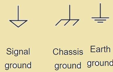
Eathf ground also called safety ground connection with real ground or earth. It is good for safety and offers a path for current to dissipate in the ground easily if there is a fault in the circuit. Earth ground is shown with three-pronged plug-in electrical devices, whose one leg is connected to the ground connection. This ground protects people and devices by making less resistance paths for current flow due to faults to cause harmful volts. These grounds are commonly used in high-voltage and power distribution circuits
This ground is the connection with the metallic frame of devices. In some electrical circuits chassis is used as a reference for ground reduces the EMI or electromagnetic interference and makes a common reference point for different components of circuits. This ground is the main part of devices that comes with an enclosed metal body and saves from electrical shock due to leakage current. It is connected to the earth's ground.
This ground is used for low-level signal circuits and as a PCB board reference node. The system has analog and digital signals, these grounds are used to separate signals to reduce the chances of interference and maintain the quality of the signal. These ground on board provide low impedance returning pat to the power supply.
Digital signals vary and cause current spikes in circuits. Due to load fluctuation current high peaks are generated in analog circuits. There are different techniques used to make proper going first make a difference between high noise current and low noise current for mixed-signal earthing. According to Ohm law voltage varies noise if these ground currents are moving to the ground returning path.
Single grounding points are used for analog and digital signals. But it is difficult to use practically the other method is to use bus bar. Note that physical separation for analog and digital grounds is not needed since return current is managed through accurate design of the board if the board design has a single ground plane
The power source that has three pins is for new students and is difficult to use. The positive, negative, and ground terminal it has. Earth or ground pins are connected with the chassis, which is then connected with earth wire in the power adapter. It is connected to the earth through the three-prong socket. The common mistake made by new engineers is that they make connections between positive and ground terminals. that is error connection does not allow the current to return to a power source so zero current flow. The accurate connection method connects the negative and positive terminals at the terminal of loads.
Electrostatic discharge (ESD) is a very common problem in electronic circuits that is due to faulty grounding techniques. it occurs if static current accumulates on an object and gets discharged on a sensitive electrical component. As a result discharge devices are damaged. The use of accurate grounding methods like anti-static mats and wrist straps minimizes the effect of ESD during assembly and component handling. If the design of the circuit is such that can easily handle the ESD effect on components.
The grand connected with the device also avoids ESD. If statically electrified objects connect testing instruments ESD causes. Different testing tools are sensitive and have the chance of being affected due to ESD. ESD protection of integrated circuits is made through grounded mats. That also called writs straps, grounded chairs, or ESD mats. During working with the ICs the ESD-safe jackets are also used as protection for instruments.
Ground loops are common issues with circuits that cause interference and undesired noise. The ground loop exists when there is more than one current path for the ground to make a loop. The changing field in this loop can cause undesired voltages resulting in interference in the circuit. For solving these issues it is good to make sure single point ground reference reduces impedance of the ground path.
Proper design also use of ground isolators help to remove the effect of ground loops. Voltage differences in the ground for many decks can cause high values of volts. If working on a ship deck there are many voltage variations between the ground on the electric cord and users that use a long extension lead.
|
|
|
|
|
|
|
|
|
|
|
|
|
|
|
|
|
|
|
|
|
|
|
|
|
|
|
|
|
|
|
|
|
|
|
|
|
|
|
|
The function of GND is simple it causes some issues that must be checked during its operation
If different functions of the ground are directly connected, high power circuits of the ground affect the zero reference point of ground of low power circuits in resulting interference between signals is causes..
The main parameter of an analog circuit is signal accuracy. if there is no accurate analog circuit loses its functionality. Ground CGND of an AC power source is a sine signal that varies periodically. Its voltage also does not have a constant value for zero volts. Make the connection of ground of different circuits with each other, periodically changes AC ground will move analog circuit ground AGND for variation that will affect voltage correct value of the analog signal
If the signal is weak that causes weak EMC of outer electromagnetic radiation. Strong signals have strong EMCs of electromagnetic radiation. If there is a connection of different circuits with ground GND of circuti having a strong signal interfere with GND of circuitry that has a weak signal. The result of that EMC having a weak signal is working as a strong outer EMR that increases hindrance to circuit EMC processing
The circuit has some part of the signal connection that helps the circuit to work more effectively and independently while a large number of parts reduces the features of the circuit to operate independently. In simple words, we have two circuits and both are not connected to each they work very well and if they are connected then each has an effect on the operation of other circuits. Connected circuits cause to increase in the interference between circuits and affect their reliability and operation.
|
|
|
|
|
|
|
|
|
|
|
|
|
|
|
|
|
|
|
|
In circuits, the positive and negative terms are used to show the polarity of voltage than ground. The ground is not positive or negative inherently but works as a reference point. In DC, current voltage is defined as the potential difference between two points. The point that is at high potential is called positive and the low potential point is negative. However, the ground is not always considered as zero volts and negative or positive points in the circuit defined by circuit design.
In different electrical systems ground is considered as a reference to measure volts. Voltage is calculated according to ground reference. Such as if a voltage source is connected between the circuit and the ground, voltage is measured as positive if it has a value larger than the ground potential and negative if lower than the ground.
So note that in AC systems positive and negative is less used since voltage continuously changes polarity. In an AC system reference point is normally a neutral conductor and voltage is defined in the form of a phase
In the power supply or source, one pin is denoted as ground or positive, and negative voltage is taken according to ground. For digital electronics, negative voltages are not common and ground is taken as a negative voltage value.
In electronic circuits, ground is a basic parameter that affects the operation, reliability, and safety of the system. Different types of used in electrical systems according to applications are signal ground, chassis ground, analog, and digital ground. its importance cannot be denied to find errors and issues existing with ground like ground loops and ESD. Different techniques such as accurate grounding, reducing the impedance of ground, and using protective devices ensure sure quality of the system. Also, proper design of the grounding system helps to affect the overall function and durability of electronic circuits
- How To Read Electrical Schematics
- What Are 10k Resistors and Their Advantages?
- Free PCB Assembly Offer is Now Live: Experience Reliable PCB Assembly from HQ NextPCB
- HQ NextPCB Introduces New PCB Gerber Viewer: HQDFM Online Lite Edition
Still, need help? Contact Us: support@nextpcb.com
Need a PCB or PCBA quote? Quote now


 Surface