NextPCB Capabilities
Printed Circuit Boards
NextPCB Capabilities
Printed Circuit Boards
 PCB Assembly
 Layer Buildup
 SMD-Stencils
 PCB Design-Aid & Layout
 Mechanics
 Quality
 Drills & Throughplating
 Factory & Certificate
 PCB Assembly Factory Show
Certificate
PCB Assembly Factory Show
Certificate
Support Team
Feedback:
support@nextpcb.com


Introduction
When it comes to working with electrical circuits, understanding the concept of voltage dividers is essential. Voltage dividers are a fundamental component in electronics, used to divide a voltage into smaller parts. In the world of electronic circuits, there's a really important thing called a "voltage divider." It might seem simple, but it's crucial for controlling and spreading electrical power in a precise way. It's like the key player in making sure we get the right amount of voltage. In this blog post, we will explore the operations and functions of voltage dividers, and how they are commonly used in various applications.
Voltage divider, also called a potential divider, is a kind of circuit that can create an output voltage (Vout) that's a portion of its input voltage (Vin). This happens because the input voltage is spread out among the components of the divider. A basic example of a voltage divider is when you have two resistors arranged in a row. The input voltage is applied across these resistors, and the output voltage comes from the point where they're connected.
At its core, a voltage divider is a fundamental building block in electronics, designed to divide a voltage into smaller, manageable parts. This seemingly straightforward function, however, conceals a wealth of complexity and nuance that underscores the elegance of its design and application. Whether in a simple resistive network or a sophisticated circuit, the voltage divider plays a pivotal role in maintaining the integrity of electronic systems.
Understanding voltage dividers also means understanding how voltage drop is distributed across resistors, how voltage division relates to the total resistance in the circuit, and why the formula for voltage division is one of the most practical tools in electronics design. These principles apply from beginner breadboard projects all the way to professional PCB engineering.
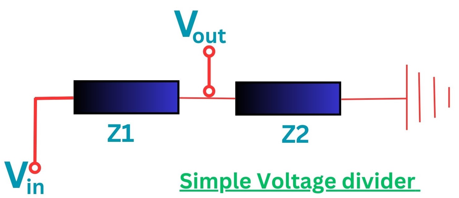
A voltage divider is a simple circuit that consists of two resistors connected in series. It is designed to divide a voltage into smaller fractions based on the ratio of the resistances. The output voltage is determined by the relationship between the resistors and the input voltage. It is a simple electronic circuit that divides a voltage into smaller parts. It consists of two resistors connected in series, with the output voltage taken from the connection between the resistors. The ratio of the resistances determines the output voltage.
Simple Voltage divider
Voltage dividers are commonly used in various electronic applications. They are used to scale down voltages, provide biasing for transistors, set reference voltages, and more. They are also used in sensors, analog-to-digital converters, and voltage regulators. Understanding voltage dividers is essential for anyone working with electronics. They are a fundamental building block in circuit design and play a crucial role in controlling voltages. So next time you come across a voltage divider in a circuit, you'll know exactly what it does and how it works.
Have you ever wondered how electronic circuits can control voltages? One of the key components that make this possible is the voltage divider circuit. A voltage divider circuit is a simple electronic circuit that allows you to divide a voltage into smaller parts. It consists of two resistors connected in series, with the output voltage taken from the junction between the resistors.
When a voltage is applied across the input of the voltage divider circuit, the voltage is divided between the two resistors based on their resistance values. The output voltage can be calculated using the formula:
Vout = Vin * (R2 / (R1 + R2))
Where Vin is the input voltage, R1 is the resistance of the first resistor, and R2 is the resistance of the second resistor.
The voltage divider circuit has various applications in electronics. It is commonly used to:
By adjusting the resistance values, you can control the output voltage and tailor it to your specific needs.
So, the next time you need to control the voltage in a circuit, remember the voltage divider circuit. It's a simple yet powerful tool that can help you achieve the desired results.
Order Authentic Components Online
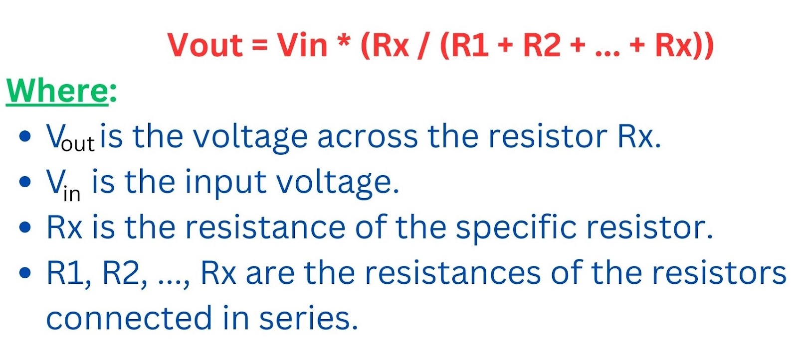
The voltage divider formula is a simple equation that helps us determine the voltage across a resistor in a series circuit. It is particularly useful when we have multiple resistors connected in series and want to know the voltage drop across a specific resistor.
The formula (equation for voltage divider) is as follows:
Voltage divider formula (equation for voltage divider)
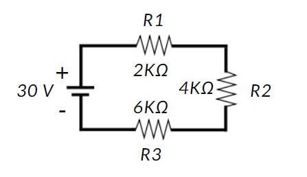
Let's say we have a series circuit with three resistors: R1 = 100 ohms, R2 = 200 ohms, and R3 = 300 ohms. The input voltage is 12 volts. We want to calculate the voltage across R2.i4
Using the voltage divider formula, we can substitute the values into the equation:
Therefore, the voltage across R2 is 4 volts.
The voltage divider formula (voltage divider equations) is a powerful tool that allows us to analyze and understand voltage distribution in series circuits. By knowing the input voltage and the resistances, we can easily calculate the voltage across any specific resistor in the circuit.
Use the interactive tool below to instantly calculate the output voltage of any voltage divider circuit. Enter your input voltage (Vin), R1, and R2 to see the output voltage (Vout), voltage drop across each resistor, and total resistance — no manual formula needed.
Voltage Divider Calculator:
The calculator applies the standard voltage divider formula: Vout = Vin × R2 / (R1 + R2). It also shows the voltage drop across R1 (which equals Vin − Vout), the total resistance of the series circuit, and the current flowing through the divider — all values you need to verify your circuit design before building.
What exactly is the voltage divider rule? It's a simple formula that allows you to determine the voltage drop across a resistor in a series circuit. By using this rule, you can easily find the voltage at a specific point in the circuit, which can be incredibly useful in various applications. The voltage divider rule is a fundamental principle in electrical engineering used to determine the voltage across one or more resistors in series. It is based on Ohm's Law and is particularly useful in analyzing simple series circuits.
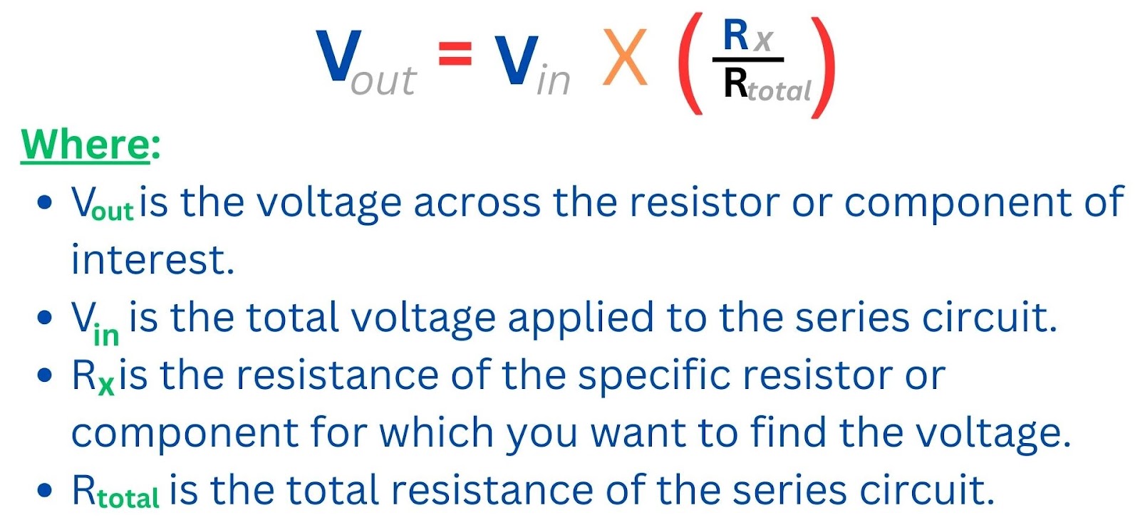
The voltage divider rule is expressed by the formula:
Voltage divider Rule
In words, the voltage across a resistor in a series circuit is proportional to the ratio of the resistance of that resistor to the total resistance in the circuit, multiplied by the total applied voltage.
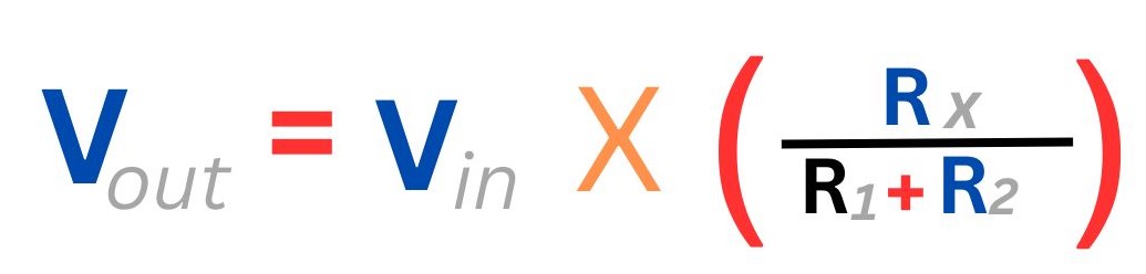
If there are only two resistors in series, the formula can be simplified to:
This rule is particularly handy when you have a voltage source connected to a series circuit with multiple resistors, and you want to find the voltage drop across a specific resistor.
Ohm's Law is a fundamental concept in the field of electronics that helps us understand the relationship between voltage, current, and resistance in an electrical circuit. Named after the German physicist Georg Simon Ohm, this law states that the current flowing through a conductor is directly proportional to the voltage applied across it and inversely proportional to the resistance of the conductor.
The mathematical equation for Ohm's Law is expressed as:
V = I x R
Where: - V represents the voltage across the conductor, (I) represents the current flowing through the conductor, and (R) represents the resistance of the conductor.
This simple equation allows us to calculate any one of the three variables if we know the values of the other two. For example, if we know the voltage and resistance in a circuit, we can use Ohm's Law to determine the current flowing through it. Ohm's Law is not only a theoretical concept but also finds practical applications in various aspects of electronics. It helps in designing and analyzing circuits, selecting appropriate components, and troubleshooting electrical problems.
|
|
|
|
|
|
|
|
|
|
|
|
|
|
|
|
|
|
|
|
|
|
|
|
As a result, the current via each resistor is 5V, 10V, and 15V, correspondingly!
Equations can sometimes be intimidating, especially when they involve complex symbols and formulas. However, there are ways to simplify equations and make them more approachable.
Voltage division is the underlying principle that makes a voltage divider work. It describes how a source voltage is shared among resistors connected in series — each resistor "takes" a portion of the total voltage proportional to its share of the total resistance.
In a series circuit, the same current (I) flows through every component. Because voltage drop equals I × R (Ohm's Law), a resistor with higher resistance will have a greater voltage drop. This is the essence of voltage division: resistance ratios directly control how the voltage is divided.
Where Vx is the voltage drop across any specific resistor Rx, and the denominator is the sum of all resistances in the series chain (total resistance). This formula generalizes to any number of resistors, making voltage division analysis applicable to complex multi-stage circuits.
| Feature | Voltage Division (Series) | Current Division (Parallel) |
|---|---|---|
| Circuit type | Series resistors | Parallel resistors |
| What is shared? | Voltage is divided; current is same | Current is divided; voltage is same |
| Formula variable | Vx = V × (Rx / Rtotal) | Ix = I × (Rtotal / Rx) |
| Larger R gets… | More voltage drop | Less current |
| Common use | Voltage scaling, biasing | Current steering, amplifiers |
Understanding voltage division is crucial when calculating voltage drops in multi-resistor networks. For example, in a 3-resistor series circuit with a 30V supply where R1 = 10Ω, R2 = 10Ω, and R3 = 10Ω, each resistor sees exactly 10V — a perfect three-way voltage division because the resistances are equal.
Voltage dividers are a fundamental circuit element used in various applications to divide a larger voltage into smaller, more manageable voltages. They consist of a series of resistors connected in series, with the output voltage taken from the junction between two resistors. Voltage dividers circuits are very common and are found in many applications. Here are some common applications of voltage dividers and how they are used in different scenarios.
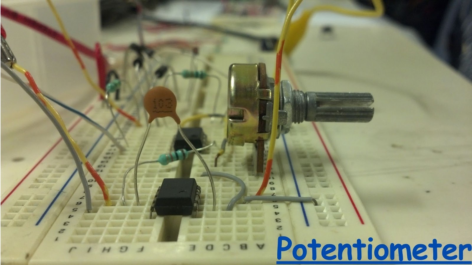
Potentiometers are versatile electronic components that are commonly used in various applications, including audio equipment, dimmer switches, and volume controls. They are also known as pots or variable resistors. A potentiometer consists of a resistive track and a sliding contact, which is usually controlled by a knob or a slider. By adjusting the position of the sliding contact, the resistance can be varied, allowing for precise control over the output voltage or current.
Voltage Dividers Potentiometers
There are several types of potentiometers available, including rotary potentiometers, slide potentiometers, and trimmer potentiometers. Rotary potentiometers are the most common type and are often used for volume controls and tone adjustments in audio equipment. Slide potentiometers are linear and are commonly found in faders and sliders. Trimmer potentiometers are small and are used for fine-tuning circuits during assembly or repair.
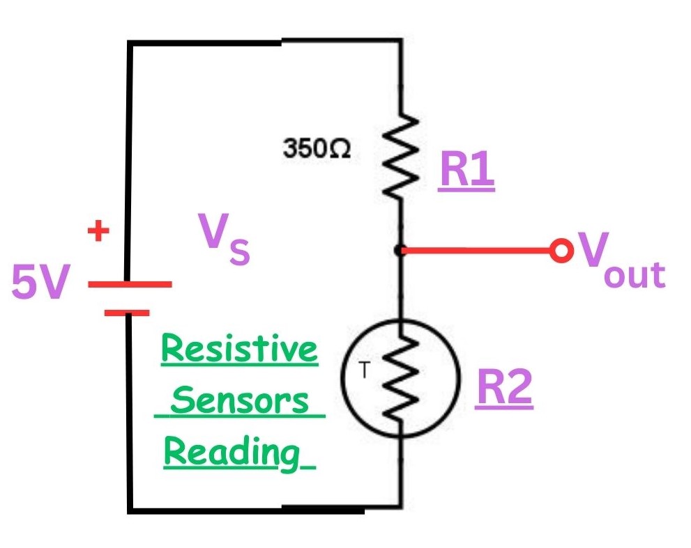
Many sensors operate based on resistance, while microcontrollers typically measure voltage rather than resistance. To bridge this gap, resistive sensors are commonly integrated into voltage divider circuits alongside resistors. This configuration enables a seamless interface with microcontrollers. An illustrative example of such a setup is presented below.
Resistive Sensors Reading
A thermistor is a temperature-sensitive sensor that exhibits a proportional change in resistance with temperature. Assuming the thermistor has an initial resistance of 350Ω at room temperature, a matching resistor is selected to also be 350Ω.
At room temperature, the output voltage is calculated using a voltage divider formula:
Vout = (5 X (350Ω / 350Ω + 350Ω)) = 2.5V
As the temperature increases and the thermistor resistance becomes 350.03Ω, the output voltage changes to:
Vout = (5 X (350.03Ω / 350Ω + 350.03Ω)) = 2.636V
Although this change in voltage is relatively small, it remains detectable by a microcontroller. With knowledge of the thermistor transfer function, the corresponding temperature can be accurately calculated.
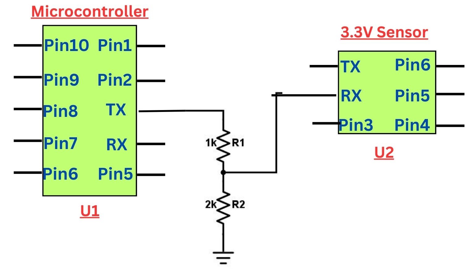
Voltage dividers prove beneficial in situations requiring voltage reduction, especially when interfacing signals between a sensor and a microcontroller with disparate voltage levels. For instance, many microcontrollers function at 5V, whereas certain sensors can only handle a maximum voltage of 3.3V. To prevent potential damage to the sensor, it becomes essential to level down the voltage originating from the microcontroller. An illustrative circuit demonstrating this voltage leveling is presented below.
Level Shifters
The depicted circuit features a voltage divider comprising a 2kΩ resistor and a 1kΩ resistor. Assuming the incoming voltage from the microcontroller is 5V, the resultant leveled-down voltage supplied to the sensor is determined as follows.
Vout = (5 X (2kΩ / 2kΩ + 1kΩ)) = 3.33V
This adjusted voltage level is deemed safe for the sensor's specifications. It's important to emphasize that this circuit is designed specifically for reducing voltage levels and is not applicable for increasing them.
Voltage drop is one of the most important concepts to understand when working with voltage dividers. In any resistor divider circuit, the total input voltage is distributed as individual voltage drops across each resistor in the series chain. The sum of all voltage drops always equals the total supply voltage — this is a direct consequence of Kirchhoff's Voltage Law (KVL).
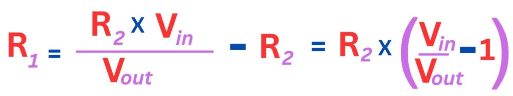
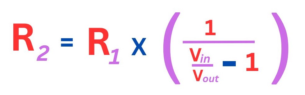
To calculate the voltage drop across R1 in a standard two-resistor voltage divider, you can use either of two equivalent methods:
The voltage drop across R2 is simply Vout itself — the output of the divider is taken directly across R2, so these values are the same.
Suppose we have a 12V supply with R1 = 8kΩ and R2 = 4kΩ. Let's calculate all voltage drops step by step:
Notice how the voltage drops are proportional to the resistances: R1 is twice the size of R2, so the voltage drop across R1 is exactly twice the voltage drop across R2. This proportionality is the core of the voltage divider rule.
Excessive voltage drop in a divider can cause problems in real circuits. If the total resistance of R1 + R2 is too low, a large current flows constantly through the divider — wasting power and potentially overheating resistors. If the total resistance is too high, the output voltage becomes sensitive to the load (any device connected to Vout), because even a moderate load resistance can pull Vout significantly below the calculated value.
| Scenario | Effect on Voltage Drop | Consequence |
|---|---|---|
| Rtotal too low | High current, large power dissipation | Wasted energy, resistor heating |
| Rtotal too high | Low current, but load-sensitive Vout | Output sags when load is connected |
| Rtotal = 10× Rload | Balanced current vs. accuracy | Recommended design rule |
Understanding voltage drop also helps with power dissipation calculations. Each resistor dissipates power equal to P = Vdrop² / R, or equivalently P = I² × R. In a 12V divider with 1mA current, R1 (8kΩ) dissipates 8mW and R2 (4kΩ) dissipates 4mW — both well within the 250mW rating of a standard ¼W resistor, confirming the design is safe.
In conclusion, voltage dividers are an essential component of electronic circuits. They are used to create reference voltages, reduce the magnitude of a voltage, and measure voltage. The voltage divider formula, voltage divider rule, voltage divider equations and Ohm’s law are used to calculate the output voltage, voltage across each resistor, and current flowing through a resistor in a voltage divider circuit. Voltage dividers have many applications, including potentiometers, resistive sensors reading, and level shifters.
The voltage divider rule states that the voltage across each resistor in a series circuit is proportional to its resistance. The rule is used to calculate the voltage across each resistor in a series circuit. Ohm’s law is used to calculate the current flowing through a resistor in a voltage divider circuit. Voltage dividers have many applications, including potentiometers, resistive sensors reading, and level shifters. A potentiometer is a three-terminal resistor with a sliding or rotating contact that forms an adjustable voltage divider.
Still, need help? Contact Us: support@nextpcb.com
Need a PCB or PCBA quote? Quote now


 Surface