NextPCB Capabilities
Printed Circuit Boards
NextPCB Capabilities
Printed Circuit Boards
 PCB Assembly
 Layer Buildup
 SMD-Stencils
 PCB Design-Aid & Layout
 Mechanics
 Quality
 Drills & Throughplating
 Factory & Certificate
 PCB Assembly Factory Show
Certificate
PCB Assembly Factory Show
Certificate

Support Team
Feedback:
support@nextpcb.com


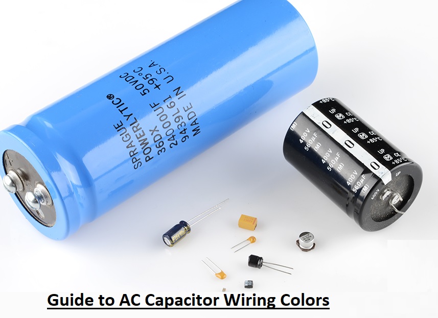
Capacitors are fundamental passive components that have the vital feature to store electrical energy in the form of an electrical field. This characteristic makes them exceptionally useful across a wide array of electronic and electromechanical circuits. Structurally, a capacitor features two conductive plates separated by an insulating material known as a dielectric. The conductive plates are typically made of metallic materials, and when voltage is applied to these plates, they accumulate an electrical charge.
In the realm of high-power applications, particularly in Heating, Ventilation, and Air Conditioning (HVAC) systems, large external capacitors are critical for motor operation. At the same time, these massive components must interface seamlessly with sophisticated control boards manufactured via high-precision PCB assembly (PCBA) processes. Here, we will cover the intricate details of AC capacitor wiring colors, how they function, and how they relate to the broader scope of electronic hardware design and manufacturing.
The AC capacitor is a very important component of any HVAC system since it directly controls the operational efficiency of the compressor and fan motors. If there is a faulty AC capacitor, there is an immediate need to change it. Malfunctioning AC capacitors struggle to provide cool air. It can cause high power consumption, severe damage to the AC unit, and ultimately lead to AC freezing issues.
The physical structure of a large HVAC run capacitor and its energy-delivery operation are somewhat like those of a battery, but they are not batteries. The connection of capacitors is made with specific wiring harnesses in the air conditioning system, which are ultimately controlled by relays or solid-state switches located on the main control PCB. The AC capacitor comes with a high voltage rating (often 370V or 440V) and is highly dangerous. If it is not accurately handled and touched by mistake, it can cause serious or fatal electrical shock.
Fundamentally, the capacitor is an electrical component in an AC unit that provides a motor with an additional power boost to start and work accurately. Based on the specific HVAC motor architecture, the quantity and type of capacitors will differ. Most modern HVAC systems come with one inducer motor and another connected to a fan motor. One single capacitor might be used for the compressor motor and condenser fan motor (a dual run capacitor), or two separate individual capacitors may be utilized. The switching logic that dictates when these motors receive power is programmed into the system's microcontroller, physically mounted on a printed circuit board (PCB).
Get Instant PCB Online Quote for Motor Control Boards
The capacitor symbol on a schematic and a battery symbol look somewhat similar, and their high-level operations can also be compared, as both store energy. However, the dynamics are entirely different. The capacitor releases energy very quickly—usually in fractions of a second—while the battery releases energy slowly over a longer period of time. High-speed energy releases help the heavy inductive motor fulfill its massive energy needs during startup.
In AC units and HVAC systems, the main use of AC capacitors is to deliver current to motors that need an additional phase shift and current surge during starting conditions. The capacitors provide additional energy, get recharged by the alternating current, and then again boost electricity to maintain the motor's rotational magnetic field. Based on the HVAC system's design requirements, there can be a need for an AC starter capacitor, an AC dual capacitor, or an AC run capacitor. As of 2026, with the enforcement of stricter SEER2 (Seasonal Energy Efficiency Ratio) standards, the precision of these capacitors and the fast-response turnkey PCB assemblies controlling them are more vital than ever to reduce energy waste.
When discussing AC equipment, hardware developers must distinguish between the massive external metal-can capacitors used for motors and the smaller board-level capacitors used in PCB manufacturing.
This capacitor comes with polarity and has positive and negative signs. It is used to make DC volts smooth after the voltage rectification process on the control board. It helps to decrease the ripples from the DC power source. The larger the capacitance of the capacitor, the less ripple it will allow. It is widely used in simple linear power sources with step-down transformers mounted directly on the PCB.
These board-level capacitors are used as bypass capacitors for bypassing high-frequency noise in control circuits. They are connected in a parallel combination across the DC power intake of Microcontrollers (ICs) to bypass certain values of frequency noise that can have a bad effect on digital logic circuits. Power supplies without transformers (capacitive dropper circuits) commonly use them since they offer good efficiency in a small footprint. Surface-mount ceramic capacitors (SMDs) are essential components in high-density multilayer PCB boards used for smart thermostats.
These capacitors are commonly used in inverter control circuits within modern AC units. They are defined as Class X (line-to-line) or Class Y (line-to-ground) types and are used in the main EMI filter part of circuits. During their handling and PCBA testing, be careful since a charge on this capacitor can cause a shock even when main power is cut off. Make sure accurate certifications like VDE, UL, or CE markings exist on the structure of the capacitor before connecting them in circuits or specifying them in your Bill of Materials (BOM). This capacitor, often paired with common-mode inductor coils, is used to decrease the harmonics that are produced due to the fast switching of the AC power source through onboard IGBTs or MOSFETs.
These are the large, external capacitors used in single-phase electric motors. The start capacitor is used for shifting the phase difference between the starting and running windings of the capacitor-start motor. This electrical phase difference results in a high starting torque, which is absolutely necessary to start the motor when the compressor is under full refrigerant pressure load.
The run AC capacitor remains in the circuit and is used for shifting the phase difference between windings continuously, allowing the motor to run smoothly with higher efficiency. The markings on the single-phase compressor help hardware engineers find connections to the motor. The standard labels are: R used for the Run winding connection, S for the Start winding connection, and C used for the Common terminal of the two windings.
The AC capacitor wiring colors are normally based on industry convention; the color of the wiring indicates that certain terminals have a specific function when making connections between the control PCBA, the contactor, and the motor. It must be noted that while standards exist, each manufacturer might occasionally use different colors of wires for different functions, so verifying against the system schematic is crucial.
Normally used color codes for AC capacitor terminals in North American and international HVAC systems are listed here:
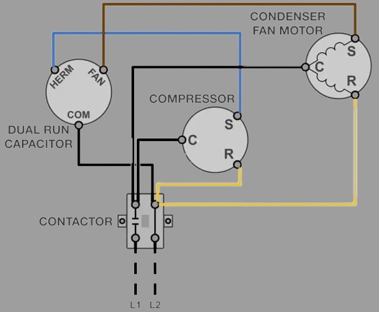
There are different parts of an AC capacitor circuit, and it is not always easy to trace the operation of an electrical circuit visually. The AC capacitor wiring color diagram defines all terminals on the capacitor with their exact wiring connection from the capacitor to the motor of the fan, the compressor, the power source contactor, and the connected load.
The color code of the wires in the diagram is related to the color code of the wires on real capacitors and wiring harnesses. For example, black wire is used to show the common terminal, brown is used to show the FAN connection, and the red wire is shown connecting to HERM. This diagram is also used to show the connection of other connected components of a circuit, like a potential relay, the defrost control board, and the main power PCBA. The connection is denoted by simple lines connecting one component to another.
As a hardware developer or field engineer, it is important to note that some different manufacturers and countries use different colors for different terminals. Therefore, before using a capacitor in the circuit or spinning a new turnkey PCB assembly for an aftermarket controller, always read the color coding for each terminal on the OEM schematic. If an accurate connection is not made, it can severely affect the device, destroy the control board, and burn out the motor.
The wiring of a dual-run capacitor is slightly different from that of a standard single capacitor because it houses two independent capacitors in one physical aluminum can, sharing a single common terminal. Follow these engineering points to make a correct connection for dual-capacitor wiring:
For electronics engineers designing the control systems that manage these high-power AC capacitors, standard PCB manufacturing rules do not apply. The surge currents involved in starting a 3-ton compressor can exceed 70 to 100 Amps for a fraction of a second.
The health of an AC capacitor is best monitored with the use of a high-quality digital multimeter equipped with a capacitance setting. A multimeter is a standard device used by electronics engineers and technicians for measuring various electrical parameters. An AC capacitor's capacitance is measured in microfarads (µF or MFD).
There are different techniques used to test AC capacitors. One technique is performed when the circuit is in a live state (under load), and another safer method is used when the circuit is completely powered off. Any method used to test must be done professionally; because when the capacitor is separated from the circuit, the electrical charge stored inside can still have a dangerously high value. Always discharge the capacitor safely using a bleed resistor before handling.
For bench testing, the separated AC capacitor is connected to a multimeter set to the microfarad reading mode. Then the capacitor must be checked between the Common (C) terminal and the other points (HERM or FAN). Based on the capacitor rating, it has different expected values for different terminals. The measured reading between the C pin and other pins of the capacitors is displayed in microfarads.
During the checking of the capacitor, if the circuit is actively operating (live testing under load), there is a mathematical expression used by technicians to test it based on the amperage of the motor. You take the measured Amps on the start wire, multiply by 2,652, and divide by the voltage measured across the capacitor terminals.
Formula: Microfarad rating = (AMPS * 2,652) / Voltage
Every capacitor comes with its specific microfarad rating printed on the label, which defines the accurate function of the capacitor. Most run capacitors are designed to operate within a tight tolerance of plus or minus five to ten percent (+/- 5% or 10%) of the mentioned microfarad rating. If a capacitor is tested and the result value is not within this specific percentage range, it has degraded (high ESR or dielectric loss) and must be replaced immediately to save the motor and the control board.
Working with high-voltage electronics requires strict adherence to safety protocols.
The fan and compressor capacitor must be connected carefully during motor installation or service. It is best to note the details of wire colors and terminal connections before beginning.
The start or run capacitor can be linked together into one physical unit, called a dual capacitor with 3 pin groupings, but the functions can also be split between two different standalone capacitors. The start capacitor provides the fan or compressor motor with a massive burst of phase-shifted torque that is needed to start the heavy rotor spinning against mechanical resistance. Once the motor reaches about 75% of its operating speed, a potential relay (often mounted on the system's PCBA) takes the start capacitor out of the circuit.
The run capacitor stays on, and it continuously provides the motor with the optimal phase shift required to maintain a smooth, efficient rotating magnetic field. If the start capacitor or its controlling relay is affected, the motor will simply hum and will not be turned on, eventually tripping the thermal overload switch. If the run capacitor is bad or degrading, then the motor might get turned on, but the operating amps drawn through the system will be much larger than normal. This results in the motor overheating and drastically reducing its operating life. As a best practice, when the condensation fan motor or compressor is replaced, a new start/run capacitor must be connected to protect the new investment.
1. What happens if you wire an AC capacitor wrong?
Wiring an AC capacitor incorrectly can lead to immediate motor failure, the motor running backward, or the compressor drawing excessive locked-rotor amps (LRA). This massive current draw will usually trip the circuit breaker, overheat the wiring, or severely damage the relays on the main HVAC control PCB.
2. Can I use a 440V capacitor in place of a 370V?
Yes. The voltage rating on a capacitor is the maximum voltage it can safely handle. You can safely upgrade a 370V capacitor to a 440V capacitor of the exact same microfarad (MFD) rating. However, you can never replace a 440V capacitor with a 370V unit, as the dielectric will break down.
3. How does the HVAC control board (PCBA) interact with the capacitor?
The PCBA operates on low voltage (typically 24VAC). When the thermostat calls for cooling, the microcontroller on the PCBA sends 24V to the coil of a heavy-duty contactor. When the contactor pulls in, it sends high voltage (240V) to the common terminal of the capacitor and the common wire of the motors, activating the system.
4. Does polarity matter on an AC run capacitor?
No. Standard AC run and dual-run capacitors are non-polarized because they operate on alternating current. However, terminal designation absolutely matters (C, HERM, FAN) to ensure the correct microfarad rating goes to the correct motor winding.
Proper maintenance, regular testing, and the replacement of faulty capacitors at the proper time are the best practices for the effective, long-lasting operation of any HVAC system. By strictly following safety measures, accurately diagnosing capacitor degradation, and relying on standardized wiring techniques, technicians help to maintain reliable HVAC infrastructure. Therefore, it is highly preferred that consumers get the services of an HVAC expert to make sure of accurate capacitor connections and system integration.
For hardware engineers, the AC capacitor's color code wiring is a standard that dictates the operation of the terminal that is connected to the control electronics. It is critical to carefully check the wiring diagram of specific devices during the design phase to make sure the wire routing logic on your control board is correct. If the switching logic or the PCBA trace widths are not correct, it can catastrophically damage the entire system.
If you are an electronics engineer or hardware developer designing the next generation of smart thermostats, inverter AC motor controllers, or HVAC relay boards, the quality of your bare boards and assembly process cannot be compromised. NextPCB provides industry-leading PCB manufacturing and turnkey PCB assembly (PCBA) services. From heavy copper boards required for high-current relays to the precise placement of surface-mount safety capacitors, NextPCB ensures your control electronics are as robust as the heavy machinery they operate.
Get Your Quick Turn PCB & PCBA Quote from NextPCB Today
Still, need help? Contact Us: support@nextpcb.com
Need a PCB or PCBA quote? Quote now