- Table of Contents
- Introduction: The Engineer's First Line of Defense
- What Is a Multimeter in Hardware Development?
- Anatomy of a Multimeter: Key Parts for Testing
- Basic Multimeter Symbols and Their Meanings
- Advanced Multimeter Symbols for Complex PCBA
- Understanding Multimeter Units
- What Does 200m Mean on a Multimeter?
- Practical PCB Troubleshooting: A Real-World Engineering Case
- Why Manual Testing Complements Professional PCB Manufacturing
- Frequently Asked Questions (FAQs)
Introduction: The Engineer's First Line of Defense
A multimeter is the cornerstone tool of electronic engineering, utilized to measure different parameters of electrical-based values across circuits. When evaluating a newly fabricated printed circuit board or debugging a complex prototype, the multimeter is indispensable. However, there are different symbols printed on the meter's interface that are employed to define the values of various parameters. The large number of symbols, abbreviations, and units can make it difficult for any new electronic enthusiast, procurement specialist, or junior hardware developer to learn their operation and uses.
As we navigate through 2026, with the increasing density of high-speed digital designs and IoT miniaturization, accurate manual probing is more critical than ever before sending a design out for mass PCB manufacturing. Here, we will explain each symbol in detail, its related function, and how it applies to real-world PCB troubleshooting. Let's get started!
What Is a Multimeter in Hardware Development?
The short form of the multimeter is a "multiple-meter." It is a versatile electronic measuring instrument used to measure different parameters of an electrical current. In the context of hardware development, it is used to measure and verify different features of raw circuit boards, populated components, and power delivery networks. It fundamentally measures current in amperes, voltage in volts, and resistance in ohms.
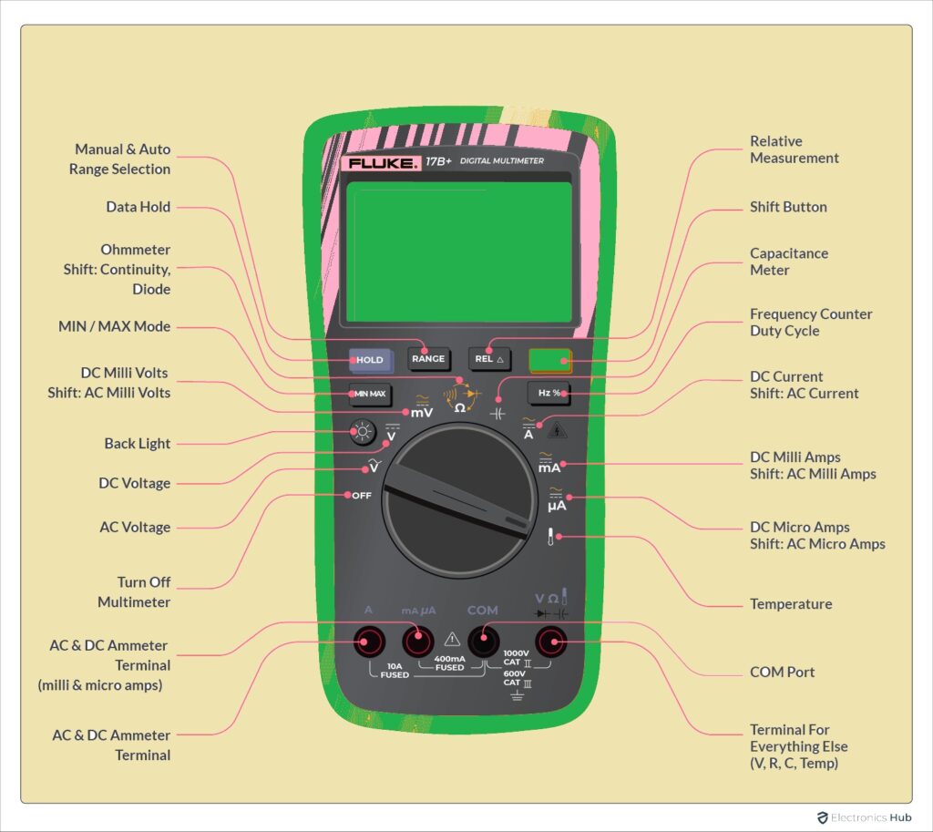
There are four main parts of this meter. The first one is the display screen that shows the calculated values. Secondly, there are function buttons used to turn it on and off, or hold values. Thirdly, it features a rotary selection dial used to vary the measuring unit and range. Finally, it utilizes two test leads (probes) that are used for physically testing connections, solder joints, and components on your PCB.
Anatomy of a Multimeter: Key Parts for Testing
Before diving into the symbols, understanding the physical parts of the meter is crucial for any hardware developer looking to test a PCBA (Printed Circuit Board Assembly). Different parts of the meter are used to find values of different electrical parameters. Those are listed here:
- - Analog Display: In the analog meter display, a movable needle gives the measured value on a printed scale. While less common in modern digital labs, they are still favored by some analog engineers for observing rapidly changing voltages.
- - Digital Display: In a digital multimeter (DMM), the measured value is shown in the form of precise numbers. It comes with digits and symbols (used for units) that show the values measured, offering high accuracy essential for low-voltage components.
- Selection Dial (Function/Range Selector):
- - It is used to select the meter's required measured function or unit like current, voltage, resistance, and value range. Selecting an accurate range is important to measure values correctly and avoid blowing internal fuses.
- - In digital meters, there are some extra buttons such as HOLD, used for holding the reading on the screen, choosing a certain range manually, or turning on the backlight button for dark lab environments.
- - In an auto-ranging meter, the device automatically selects the most accurate range for measuring the value. It minimizes the use of manual range selection, saving engineers time during rapid prototyping.
- - Power is provided to the meter through internal batteries. Ensure this is checked regularly, as low battery voltage can cause a DMM to display inaccurate resistance readings on a circuit board.
- - Common (COM): This is the common terminal that acts as the reference point (ground) for any measured value. The black probe is always inserted here.
- - Volts/Ohms/Amps (VΩmA): These input jacks are used to measure voltage, resistance, and smaller currents. Before finding the required value, first select the jack according to the function, then connect the red probe. A separate jack (often labeled 10A) is used for high-current measurements.
- - These test leads are attached to input jacks and used for establishing an electrical connection with the required circuit. They are color-coded: red is positive, and black is the negative (common) lead. For testing fine-pitch SMD components on a modern PCB assembly, needle-tipped probes are highly recommended.
- - There is a fast-acting fuse connected in the current paths to protect the meter from high current surges if connected improperly.
Click Here to Get an Instant Online Quote for Your PCB Project at NextPCB
Basic Multimeter Symbols and Their Meanings
Understanding these basic symbols is the first step toward effective Design for Manufacturing (DFM) verification. Being able to quickly read these symbols allows you to verify components before they undergo the reflow soldering process.
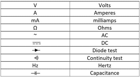
- DC Voltage (V with straight lines): It measures Direct Current (DC) volts and is denoted with the capital letter V, three hyphens, and a straight line on top. Move your dial to this symbol to check battery levels, power supply outputs, or voltage drops across a PCB trace.
- AC Voltage (V~ or mV~): It is used to measure Alternating Current (AC) voltage. It is denoted with a V or mV having a wavy line (tilde) on top. It is used to measure the voltage of AC signals, especially checking mains power inputs or low-value analog signals in audio circuits.
- Resistance (Ω): It is used to measure the electrical resistance of circuit components. It is denoted with the Greek letter Omega (Ω). Move the dial to this symbol to verify resistor values before soldering or to ensure a trace has negligible resistance. It is also used to check whether a fuse is intact or blown.
- DC Current (A with straight lines): It measures DC amperage. It is denoted with an A having three hyphens and a straight line at the top. To measure the power consumption of a micro-controller on your prototype, place the meter in series with the circuit using this setting.
- Diode Test (Arrow with a line): This is used to test semiconductor diodes and LEDs on the circuit. It often shares space with the continuity symbol and looks like an arrow pointing at a vertical line (the schematic symbol for a diode). It displays the forward voltage drop. Using this symbol, we can determine whether a diode is functioning, installed backward, or destroyed.
- Continuity Test (Sound wave symbol): Denoted with a series of parallel arcs (like a Wi-Fi or sound wave symbol), it measures the electrical continuity between two points. If the path is unbroken, the meter emits a loud beep. This is arguably the most important function for finding faults—such as solder bridges (shorts) or broken traces (opens)—on a newly received quick turn PCB.
- Current Gain (hFE): It is used to find the DC current gain of a bipolar junction transistor (BJT) connected in the circuit.
- Hold: Used to freeze the display and retain the current measured reading on the screen. Very useful when your eyes need to focus on probing tiny vias rather than looking at the screen.
- Brightness / Backlight Button: Used for adjusting the screen brightness. It is the best option for meter use in low-light lab environments or outdoor industrial settings.
- OFF: Used to power off the multimeter to preserve battery life.
Advanced Multimeter Symbols for Complex PCBA
As electronic designs in 2026 demand higher precision—such as RF modules, motor controllers, and dense power management ICs—engineers frequently rely on advanced DMM functions.
- AC Current (A~): This symbol (an A with a wavy line) represents the meter's ability to measure alternating current. It is commonly used when dealing with inverters, mains-powered power supplies, and heavy industrial controls.
- Temperature Symbol (°C / °F): Used to measure system thermals. It requires a specific thermocouple probe (usually K-type). Engineers use this to monitor the heat dissipation of voltage regulators and MOSFETs during the burn-in testing of a PCBA.
- Capacitance Symbol (-||-): This symbol (two parallel lines resembling a capacitor) is used to find the value of capacitance in Farads. It determines how much electrical charge a capacitor can store. It is vital for verifying decoupling capacitors on high-speed digital boards to ensure signal integrity.
- Hz Symbol (Frequency): This represents Hertz and is used to measure the frequency of an electrical signal. Hardware developers use this to check clock signals, PWM outputs from microcontrollers, and oscillator stability.
- Duty Cycle (%): This denotes the duty cycle feature. The ratio of the duration of a signal's "high" state to the total time of the signal's period is called the duty cycle. It is highly useful for verifying motor control signals and LED dimming circuits.
Understanding Multimeter Units
Students, new learners, and even purchasing managers reading component BOMs (Bill of Materials) may face difficulty decoding the metric prefixes used on meters and schematic diagrams. You will rarely see base units without prefixes because electronics deal with vast extremes of values.
The base units are V for Voltage, Ω for Resistance, and A for Current. These units are accompanied by standard metric prefixes:
- K (Kilo): Means 1,000 times the base unit. (e.g., 10 KΩ = 10,000 ohms)
- M (Mega): Means 1,000,000 times the base unit. (e.g., 1 MΩ = 1,000,000 ohms)
- m (milli): Means 1/1,000 of the base unit. (e.g., 50 mA = 0.05 Amps)
- μ (micro): Means 1/1,000,000 of the base unit. (e.g., 10 μF = 0.000010 Farads)
- n (nano) and p (pico): Frequently seen in capacitance, meaning one-billionth and one-trillionth respectively.
What Does 200m Mean on a Multimeter?
If there is "200m" written on the selection dial of the meter, it indicates a maximum measuring range for that specific setting. Here, "m" stands for milliunits (1/1000).
If you have to measure voltage and the dial is set to 200m in the DC Voltage section, it means the highest value the meter can measure on that setting is 200 millivolts (0.2 Volts). If you attempt to measure a standard 3.3V logic line on this setting, the meter will likely display a "1" or "OL" (Over Load) to indicate the measurement is out of range. You would need to turn the dial up to the 2V or 20V setting to get an accurate reading.
Other common manual ranges include 2000m (which is 2 units), 20, 200, and so on. Always start at a higher range if you are unsure of the circuit's exact voltage, then dial down for precision.
Practical PCB Troubleshooting: A Real-World Engineering Case
Let’s apply this knowledge. Imagine you have just received a batch of newly assembled boards from your low cost PCB supplier. You plug in the power, and nothing happens. Here is how an engineer uses the multimeter to debug:
- Visual Inspection: Look for obvious defects like tombstoned components or missing solder.
- Continuity Check (Sound Wave Symbol): Before powering on again, set the multimeter to continuity mode. Touch the red probe to the VCC (power) rail and the black probe to the GND (ground) rail. If the meter beeps continuously, you have a dead short. You must find the solder bridge before applying power, or you risk burning the board.
- Voltage Check (V with straight line): If there is no short, apply power safely. Switch to DC Voltage mode (e.g., the 20V range). Place the black probe on a ground pad and use the red probe to test the output pins of your voltage regulators. If your 5V regulator is only outputting 1.2V, you immediately know where the power delivery issue lies.
Why Manual Testing Complements Professional PCB Manufacturing
While mastering a multimeter is essential for engineers on the bench, manual probing is too slow for mass production. That is why professional turnkey PCB manufacturers integrate automated testing into their quality control workflows.
At NextPCB, once your boards pass through surface mount technology (SMT) lines, they undergo Automated Optical Inspection (AOI) to check for missing parts and bad solder joints. For electrical verification, we utilize Flying Probe Testing and In-Circuit Testing (ICT). These automated machines act like hundreds of robotic multimeters, instantly checking continuity, resistance, and capacitance across the entire board in seconds.
However, the synergy between a reliable manufacturer and a skilled engineer is what brings a successful product to market. You design and prototype using your DMM; we manufacture and guarantee the quality at scale.
Ready to turn your tested prototypes into mass production? Explore NextPCB's Turnkey PCBA Services today and ensure your hardware is built to perfection.
Frequently Asked Questions (FAQs)
Q1: What is the difference between a manual-ranging and auto-ranging multimeter?
A: A manual-ranging multimeter requires the user to select the specific measurement limit (e.g., 20V, 200V) using the dial. An auto-ranging multimeter automatically detects the signal size and adjusts the internal range to provide the most accurate reading, which is highly beneficial for fast PCBA testing.
Q2: How do I test for a short circuit on a PCB?
A: Turn your dial to the Continuity symbol (the sound wave icon). Ensure the PCB is completely powered off. Place one probe on the power trace and the other on the ground trace. If the multimeter emits a continuous beep, there is a short circuit that needs to be fixed (likely a solder bridge).
Q3: Can a multimeter check if a capacitor is bad?
A: Yes. Advanced multimeters have a Capacitance setting (-||-). First, safely discharge the capacitor. Then, connect the probes to the capacitor's leads. The reading on the screen should match the value printed on the capacitor (within its tolerance percentage). If it reads significantly lower or shows zero, the component is degraded or dead.
Q4: Why does my multimeter read "OL"?
A: "OL" stands for Open Loop or Overload. In continuity or resistance mode, it means the circuit is completely broken (infinite resistance). In voltage or current mode, it means the value you are trying to measure exceeds the range you have manually selected on the dial.
Q5: What is the most important symbol for testing a quick turn PCB prototype?
A: The DC Voltage (V-) and Continuity (sound wave) symbols are the most frequently used. Continuity verifies that traces are unbroken and solder joints are reliable, while DC Voltage confirms that power rails are supplying the correct logic levels to your microchips.

 NextPCB Capabilities
 PCB Assembly
 Layer Buildup
 SMD-Stencils
 PCB Design-Aid & Layout
 Mechanics
 Quality
 Drills & Throughplating
 Factory & Certificate
 PCB Assembly Factory Show
Certificate
PCB Assembly Factory Show
Certificate


 Surface

