NextPCB Capabilities
Printed Circuit Boards
NextPCB Capabilities
Printed Circuit Boards
 PCB Assembly
 Layer Buildup
 SMD-Stencils
 PCB Design-Aid & Layout
 Mechanics
 Quality
 Drills & Throughplating
 Factory & Certificate
 PCB Assembly Factory Show
Certificate
PCB Assembly Factory Show
Certificate
Support Team
Feedback:
support@nextpcb.com


Introduction
As engineers and electronic project makers, you must see that there are mostly pull-up and push-up resistors connected to circuits. They're used for accurate biasing input of digital gates to prevent them from floating randomly when no input is provided. In any circuit configured with a microcontroller, there is a pull-up and pull-down resistor used to communicate with external devices at the input and output terminal like in Arduino. Mostly it is configured with general-purpose input output. The use of these resistors in circuits helps us to get high or low conditions according to requirements.
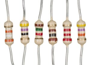
A resistor is a passive electrical component that has two terminals that provide the resistance in the circuit. In circuits resistors are used for the reduction of current flow, divides volt, signal level adjustment, biasing of active components, and termination of transmission lines. For motor controls, high power resistors are used that can dissipate high power in power distribution systems, and also in test loads for generators. The resistance of fixed resistors varies with changes in temperature operating volts and time.
Resistors are components of electrical systems and electronic circuits as the main components. Practically used resistors are discrete element that comes with different types and compounds. Resistors are also used in Integrated circuits. The function of resistors is defined by the value of resistance.
There are four main types of resistors.
The resistors offer a path to round for current to easy flow. To prevent grounding out input the resistance is effectively high so that just a small current of input passes to the ground.
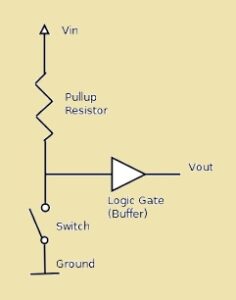
A pull-up resistor is an electronic component employed in digital circuits to ensure sure condition of the signal line when it actively operating the signal source. In digital electronics signals are denoted as zero and one that are binary numbers. But in some examples signal line can be left floating which means it not actively operating in high or low conditions. it causes undesired results of the circuit.
To solve this issue is pull-up resistor is used by providing a default high signal level when the signal line is not operating actively. it can be done by connecting the signal line with a positive power supply with resistors. If the signal line is not at a low level pull up resistors make sure that the volts on line are pulled up to positive volts denoting as one.
Pull-up resistors are used in microcontroller-based systems normally, switches, buttons, and open drain collector output devices. If the button or switch is not pressed input pin of the controller has a floating condition. Connecting the pull-up resistor between the input and VCC pins makes sure that the input has a high level of 1 when the button is open. If the button is closed it provides a low signal resistor that is effectively bypassed.
In the case of open drain or open collector structures, many devices also have a similar signal line. It can pull a line to a round or logical zero but there is no active component for pulling a line to a high value. The pull-up resistor connected between the signal line and the positive supply makes sure that the line is high when no device is in low condition.
A pull-down resistor is an electronic component used in digital circuits for the state of a Signal line if it is not operated by a signal source. In digital electronics signals are zero and one. But in some conditions signal line can be float which means it not actively operating in high or low conditions. It causes undefined results of circuits.
The pull-down resistors are used to solve this error by offering default low volts when the signal line is not actively operating. it can be done by connecting the signal line with a resistor. When the signal line is not correctly high pull done resistor make sure that volts on line are pulled down to ground or zero
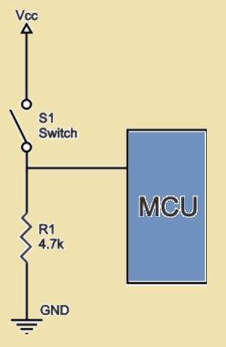
In the above diagram, you can see that the push button switch is configured with the power source and control pin. In this circuit if the switch is closed controller input is at a high value and if the switch is open pull-down resistor pulls the input voltage down to zero value, or round, eliminating the undefined condition of input. The resistance of pull pull-down resistor must be higher than the impedance of logic circuits or it can pull volts down to very high values and input volts at the pin will be constant for logically low values irrespective of switch position.
Button and Switch Inputs:
Pull-up resistors are mostly used in button and switching circuits. If the button is not pressed input pin of the controller or other digital modules has a floating condition. By making the connection of pull-up resistors to the input pin and power source there is one at input if a button is open. For the pressed button it is a low signal since the resistor is bypassed
I2C Communication:
In this protocol, many devices use the same communication lines. The pull-up resistor is used for pulling the lines high when no device is not operating them. That makes sure to define the high condition when lines are not transmitting data
Digital Sensors:
They are used in digital sensor interfaces to maintain stable volt values if a sensor is not operating the line. It has common uses like motion detectors, temperature sensors, and o digital sensors.
Open-Collector or Open-Drain Outputs:
In circuits where open collector or open drain outputs are used the connection of pull-up resistors is important. These devices can pull the line low but cannot actively make it high. The connection of Pull-up resistors in the circuit to the line makes it high when no device is pulling it low.
Microcontroller Inputs with Sensors: Pull-down resistors are used in conjunction with sensors and microcontroller inputs. When the sensor is not actively driving the input high, the pull-down resistor pulls the input to a low state (0). When the sensor activates, it overrides the pull-down effect and provides a high-level signal.
Digital Logic Gates: Pull-down resistors are used in digital logic gates to ensure a defined low state when the inputs are not actively driven. This is especially important in complex logic circuits where signals can be in various states.
Communication Protocols: Pull-down resistors are employed in communication protocols similar to pull-up resistors. For instance, in RS-485 communication, pull-down resistors are used to maintain a stable low state in the absence of an active high signal.
Unused Inputs: Unused inputs in digital circuits can be potential sources of noise or undefined states. Attaching pull-down resistors ensures these inputs remain at a defined low level, enhancing the overall stability of the circuit.
Calculating the actual values for pull-up and pull-down resistors is an important factor in digital circuit design. The use of an accurate resistor to ensure reliable and stable operation is important. Here we will solve a case study having simple button interfacing with a microcontroller input.
Case Study: Button Interface with Microcontroller
Let's suppose in circuit microcontroller has to read the condition of the push-button switch. If the button is pressed controller reads logic high 1, if not pressed it will read logic low or zero. In this condition the use of a pull-up or pull-down resistor to maintain the required voltage level when the button is in the open state or not pressed
Choosing the Resistor Value:
The selection of resistance is based on the electrical features of the input pin of microcontrollers and the power supply voltage. Normally used pull-up and pull-down resistors have values from 1k ohms to 10k ohms.
|
|
|
|
|
|
|
|
|
|
|
|
|
|
|
|
|
|
|
|
|
|
|
|
|
|
|
|
|
|
|
|
The accurate value of the pull-up or pull-down resistor is based on two factors. The first one is power dissipation. If resistance is low high current will pass through a pull up resistor that heats the device connected and high undesired power flow in a circuit. This condition is known as strong pull-up and is not applied for low-power uses. The 2nd factor is pin voltage when the switch is in open state. If pull-up resistance has a high value causes a high leakage current to the input pin and that pin can be ineffective when the switch is open. This condition is known as weak pull-up. The value of pull-up resistance is based on input pin impedance.
The simple rule is that uses at least a ten-time small resistor than the value of the impedance of the input pin. Normal bipolar logic circuits that operate at five volts normally have pull-up resistors 1 to 5 kΩ. resistive sensor uses a pull-up resistor of 1 to 10 kΩ. CMOS families that are digital circuits come with a small value of input leakage current that needs a high value of resistance like 10 kΩ to 1 MΩ
A pull-down resistor in conjunction with a switch is called a digital electronic circuit. If the switch is employed to control the digital input pin of the controller, then it needs to make sure that the input pin comes with a stable logic level that can be high or low when the switch is not actively pressed. Here pull-down resistors are used
Here's how it works:
This layout offers high (1) or low (0) logic level to the microcontroller according to the state of the switch. if the switch is in an open state pull down the resistor and make sure the input pins reading low level. If a switch is closed it connects the input pin with the positive supply and offers high-value
This configuration is mostly used in button interfaces in electronic devices. There can be designing of reliable and noise-resistant digital circuits that can be made with the use of these resistors offering correct detection of switch states.
In conclusion, the use of pull-up and pull-down resistors is a basic parameter for engineers working with digital electronics. These elements are important to ensure stable and varying behavior in digital circuits, especially when handling input signals from buttons, sensors, switches, or communication protocols.
Pull-up resistors are used when the signal has to be to a high logic level (1) for not actively driven low conditions. This layout is needed for button interfaces and open-drain communication protocols. Through the connection of the signal line to Vcc through a pull-up resistor, a floating state is removed, and reliable and noise-immune circuit operation is obtained.
Pull-down resistors are good for pulling a signal line to a low logic level if not have an actively driven high state. it is best for microcontroller inputs having sensors and digital logic gates. Connecting the signal line to the ground through a pull-down resistor makes sure of a clear low state, and avoids the error readings.
- What Are 10k Resistors and Their Advantages?
- Autumn Offer: Get $30 off PCB orders over $100 with NextPCB
- Free PCB Assembly Offer is Now Live
- HQ NextPCB Introduces New PCB Gerber Viewer: HQDFM Online Edition
Still, need help? Contact Us: support@nextpcb.com
Need a PCB or PCBA quote? Quote now


 Surface