
 NextPCB Capabilities
Printed Circuit Boards
NextPCB Capabilities
Printed Circuit Boards
 PCB Assembly
 Layer Buildup
 SMD-Stencils
 PCB Design-Aid & Layout
 Mechanics
 Quality
 Drills & Throughplating
 Factory & Certificate
 PCB Assembly Factory Show
Certificate
PCB Assembly Factory Show
Certificate
Support Team
Feedback:
support@nextpcb.com


Hi, I hope you are doing great. Printed circuit boards are the backbone of today’s modern technology. This is the result of rapid change in the working of the technical field. The demand for PCBs is now at its peak and multiple types and materials are being used for a variety of PCBs. It is obvious that people dealing with PCB production face some problems related to printed circuit boards. In this article, we will talk about some very common problems that manufacturers and designers face when they are working on PCBs. Not only this, we will give you a great list of ideas to solve each problem in the most efficient way.
The manufacturers use different types of techniques to meet the requirements of the circuit. Errors and accidents are part of every field. To deal with all the errors, expert users must know the solutions and the possible ways to deal with the issues. So, here are some very basic and possible troubleshooting for PCB problems.
In electric circuits, a short circuit means when two conductors, during the electric flow touch each other on the unwanted areas and as a result, the current starts flowing through them. This may be the cause of accidents because there are no measures taken to deal with such unwanted and unexpected areas. This may happen during the manufacturing or use of the PCB.
To deal with this problem, the users have to apply the functioning of a multimeter.
When someone observes the issue of a short circuit in PCB, they have to measure the resistance between the related conductors (either wires, traces, or components). If it is zero, then these must be separated and the PCB has to be checked critically.
This is the contrary situation to the previous one. In this, the conducting path between two or more components of the PCB is not working and as a result, the user may have infinite resistance between the components. The PCB in such conditions does not pass the current and as a result, the full functionality is not gained. This can also be solved with the help of a multimeter. Once the respected area is indicated, the components can be repaired with different techniques according to this type.
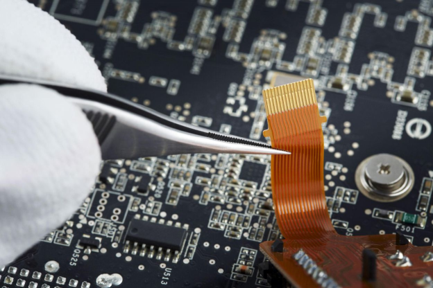
When a PCB is not working well, there may be several reasons. There must be a visual inspection when the PCB is ready to work. This is the most common and effective way to check the health of PCBs. The main focus must be on the proper orientation and seating of components, finding the burnt or incomplete path, and indicating any loose components, and related errors.
Another way to test your PCB before and during the work is to test the component’s specification and health. This can be done with the help of a multimeter. Before sending the [CB for work, one must double-check the working of components like resistors, capacitors, inductors, transistors, etc.
Every PCB has some specifications to be followed and the components have to match them. The specifications are mentioned in the instructions and if you are only checking the PCB and not the manufacturer, you have to make sure all the specifications match the manual of the PCB.
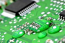
Checking for the soldering quality and its working is also a crucial step of the troubleshooting of PCB. The connectivity issues are seen when the PCB has cold solder joints, an insufficient amount of solder in between the joints, or bridges. This can be faced when cracks or damages are seen on the surface or inner areas.
The solution to this problem is to reheat the PCB at that specific point. This will help to indicate the need for a specific amount of solder in that area. If untreated, this problem can cause damage or even the breaking of PCB.
Most of the cases of PCB damage are seen while working with them. In the manufacturing process, these PCBs work but whenever a high temperature is applied to them, they may start damaging. Quality assurance must be kept in mind and during the manufacturing process, the high voltage or current has to be used on the specific components or the whole PCB.
Some components may be burnt at the high temperature of the conducting current. Moreover, the high temperature of the environment can also damage the PCB. If the circuit runs for a long time even at the right position, the components may be damaged or even the PCB is burnt in some cases. The conducting sheets or the additional layers of insulating material are the solutions to this problem. In some cases, fans are used to cool down the PCB.
This is the most useful but uncommon troubleshooting process for PCB. If someone is not able to understand the problem of PCB or has issues like a lack of components to check for the problem, they can simply take the help of any senior experts. There are different forums and communities online that can help with common problems. Moreover, if the issue is unknown to you and you want to learn practically the solution, you can go to an expert.
So, we have learned the troubleshooting of the most common but important issues related to the PCB. Some of these are related to the manufacturing process and some are related to the users. All these can be identified and solved at any level. There is a need for some tools such as multimedia and oscilloscope that helps the user to identify the issues. These measures may be life-saving in some cases. PCBs are a crucial part of our daily life and these must be designed and manufactured with great precision. In the end, if no solution is seen, one must contact the experts or the seniors or take online help but these issues may not be left untreated.
- New Automated PCB Assembly Quotation System - Order in Just a Few Steps!
- Free PCB Assembly Offer is Now Live
- HQ NextPCB Introduces New PCB Gerber Viewer: HQDFM Online Edition
Still, need help? Contact Us: support@nextpcb.com
Need a PCB or PCBA quote? Quote now


 Surface

