Contact Us
Blog >> Blog Details Page

How to Build a Flashlight Circuit?

Posted:04:26 PM April 12, 2023 writer: ​NextPCB

Flashlights are an essential tool for anyone who wants to be prepared for anything. They can be used to light up dark areas, signal for help, or even defend yourself in an emergency. But did you know that you can build your own flashlight circuit?

Building a flashlight circuit is a great way to learn about electronics and save money. It's also a fun and rewarding project that can be completed in a few hours.

In this article, we will show you how to build a simple flashlight circuit using a few common electronic components. We will also provide some tips on troubleshooting and repairing your flashlight circuit.

The following topics are covered:

Introduction to Flashlight Circuit

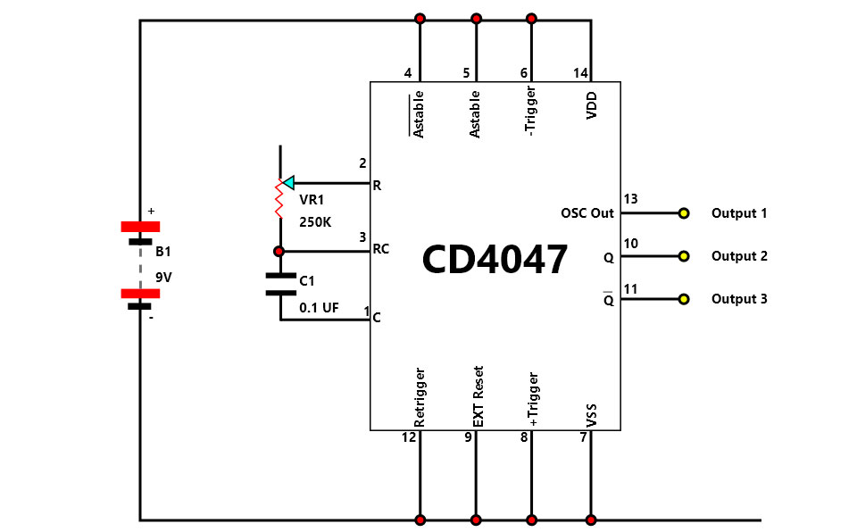
The LED flashlight circuit with an inverter IC is a convenient and effective way to convert low-voltage DC power from batteries into high-voltage AC energy for powering LED lights. This type of circuit is commonly applicable in portable flashlights due to its user-friendly design and impressive energy efficiency. The inverter IC is a fundamental piece in this circuit, as it produces the high-voltage AC signal that powers the LED light.

Functioning Flashlight

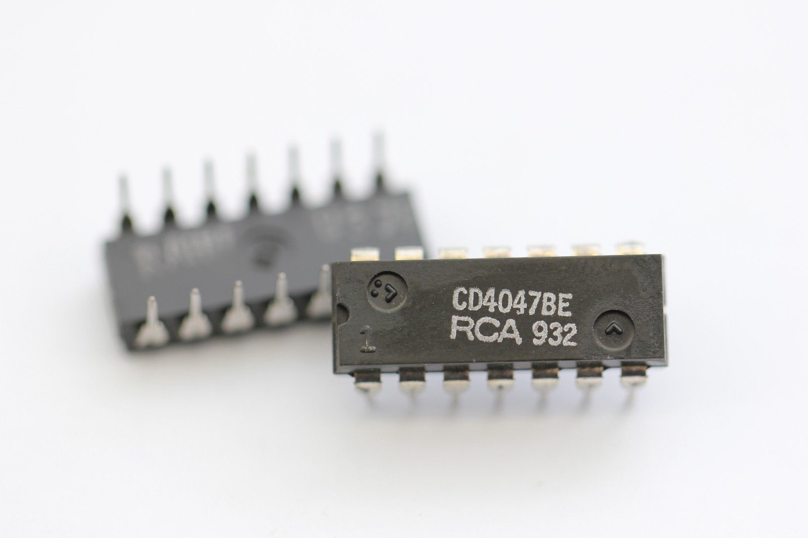
For those in search of an inverter IC, the CD4047, CD4069, and 74HC04, which are all CMOS-based devices, are the best options. These low-power integrated circuits are possible to operate using a single power supply, with the capability to output square wave signals that span frequencies from just a few Hertz up to hundreds of kilohertz! The oscillation rate of the square wave signal is contingent upon the values of external elements such as resistors and capacitors.

Create efficient lighting with minimal effort and cost by constructing a LED flashlight circuit using an inverter IC. This simple solution requires only a few essential components - resistors, capacitors, diodes, and LEDs – for impressive results. Not to mention the impressive amount of brightness emitted from this minimalistic battery power usage! With proper design and assembly, this circuit can be a reliable and useful tool for lighting in dark environments.

Understanding the Components Required for the Circuit

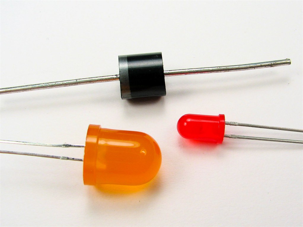
You can make your own functional LED flashlight by combining the power of an inverter IC with a few key components! To assemble this circuit, you'll need to collect some specific pieces:

  • Inverter IC: This is the heart of the circuit that generates the high-voltage AC signal required to drive the LED. As mentioned earlier, the most commonly used inverter ICs are CD4047, CD4069, and 74HC04.

Inverter IC

  • Resistors: Resistors are possible to use to limit the current flowing through the components and to set the frequency of the inverter IC. The values of resistors used in the circuit depend on the specific inverter IC used.
  • Capacitors: Electrical energy has the ability to store and release through the use of capacitors, which are essential for circuit filtering, stabilization, and setting the frequency of an inverter IC. Capacitors enable a seamless connection between power sources and loads in electrical systems by providing a buffer to store excess charge from transients or surges.
  • Diodes: In the circuit, diodes serve the purpose of protecting against reverse voltage and rectifying the AC signal generated by the inverter IC.

Diode

  • LED: The LED is the light source of the flashlight. The inverter IC generates a high-voltage AC signal required for its operation.
  • Battery: The battery is the power source for the circuit. To construct this circuit, one must consider both the voltage and current ratings of the particular inverter IC and LED used, as the selection of the battery is dependent on them.
  • PCB Board: A PCB is essential for creating a functional circuit, serving as a sturdy base that securely holds the various components together.
  • Wires and Connectors: To power up a circuit, connectors are essential for forming an electrical passageway that sends electric current from one component to the next.

Selecting the Right Type of Inverter IC for the Flashlight Circuit

Choosing the right type of inverter IC is crucial for building an efficient LED flashlight circuit. To ensure the most reliable and efficient operation, carefully consider both voltage rating and LED when selecting an inverter IC. Make sure that each matches together in order to maintain the optimal performance of your circuit!

IC Pinout

Generally, LEDs require a higher voltage than the battery voltage to operate. Therefore, the inverter IC should be capable of generating a high-voltage AC signal to drive the LED.

  • Frequency Range: The frequency range of the inverter IC should match the range required by the LED. For optimum performance and ultra-low power usage, it is crucial to accurately calibrate the frequency of the circuit by adjusting external components like resistors and capacitors. This will guarantee dazzling LED output without any flickering or wasted energy.
  • Power Consumption: The inverter IC should consume minimal power to maximize the battery life. LED flashlight circuits commonly employ CMOS-based inverter ICs, which are low-power devices that can operate from a single power supply.
  • Availability: The inverter IC should be readily available in the market. It is easy to obtain commonly used inverter ICs such as CD4047, CD4069, and 74HC04 as they are widely available in the market.
  • Cost: The cost of the inverter IC should be reasonable and within the budget for the project. The cost of the inverter IC may vary depending on the manufacturer and the specific model.

By considering these factors, you can select the appropriate inverter IC for your LED flashlight circuit that provides efficient and reliable performance. To guarantee the LED and battery used in your circuit are compatible, it is essential to consult the datasheet of the chosen inverter IC.

Design the LED Inverter Flashlight Circuit

Designing the circuit diagram is a crucial step in building an LED flashlight circuit with an inverter IC. You can follow the following steps to design the circuit diagram for an LED flashlight:

Basic Steps

  • Determine the Specifications of the LED and the Battery: Determine the voltage and current ratings of both the LED and the battery.
    These specifications will determine the values of the external components like resistors and capacitors required in the circuit.
  • Select the Inverter IC: Based on the specifications of the LED and the battery, select an appropriate inverter IC that meets the voltage and frequency requirements. 
  • Draw the Circuit Diagram: Using schematic drawing software or by hand, draw the circuit diagram showing the connections between the components. The circuit diagram must accurately display the positioning of the inverter IC, resistors, capacitors, diodes, LED, and battery for optimal performance.
  • Label the Components: Label each component in the circuit diagram to make it easy to understand.
  • Verify the Circuit Diagram: Verify the circuit diagram to ensure that it meets the specifications of the LED and the battery and that it is technically correct.

Hardware Implementation

Simple circuit diagram

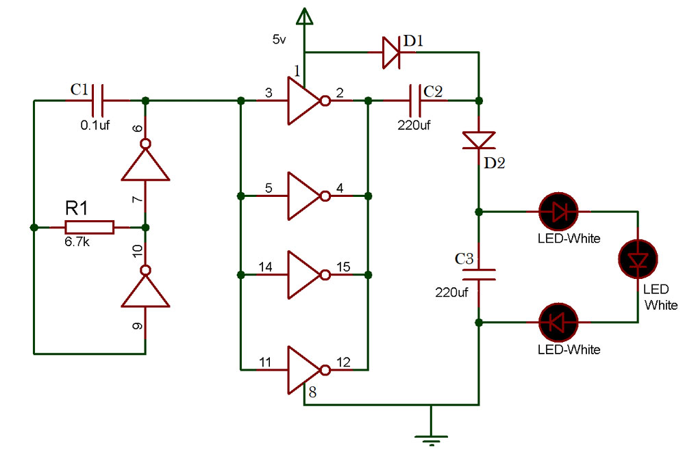
The circuit requires a 5V DC voltage input. To create the oscillator circuit, arrange resistor R1 and capacitor C1 using two NOT gates. The remaining 4 NOT gates are connected in parallel to form a buffer that doubles the input voltage. When the supply capacitor is turned on, capacitor C2 starts charging via the buffer made by the four NOT gates until it reaches the peak input voltage of 5V. Once this happens, C2 acts as a second power source of 5V, causing capacitor C3 to charge with the combined voltages of the power supply and C2, while D1 and D2 become forward-biased. Consequently, the voltage across C3 charges up to almost 10V.

Soldering the Components onto a PCB

How to Solder Component

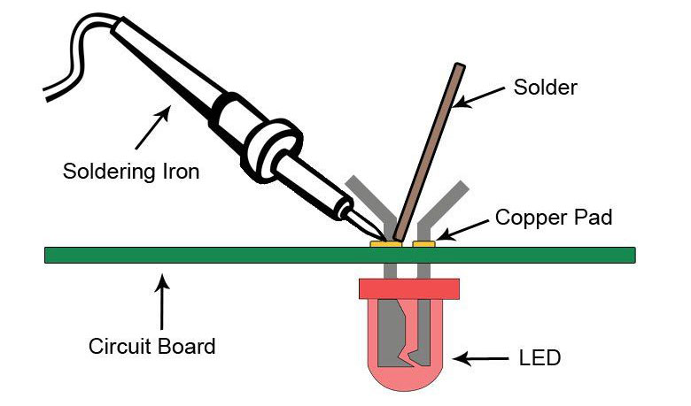
After ensuring that the circuit diagram is accurate and functional, the next stage is to assemble the design onto a circuit board by soldering each component into place. The following steps are possible to solder the components onto a PCB:

  • Prepare the PCB: Clean the PCB thoroughly to remove any dirt or debris. Then, apply a thin layer of flux to the copper traces on the PCB. Flux helps to remove any oxide layer on the copper traces and aids in the soldering process.
  • Place the Components on the PCB: Using the circuit diagram as a reference, place the components on the PCB. Ensure that you properly assemble the components in the correct arrangement.

Taking one component at a time, begin soldering them together. To join the pieces evenly and securely, apply heat from your soldering iron to the joint until the solder melts and cascades over it. The desired result should be an even coating of metallic alloy that is glossy in appearance. Take care not to use too much heat as this can cause irreparable damage to your components!

  • Trim the Leads: After soldering the joint, use a wire cutter to trim any excess leads. Ensure that there are no sharp edges or protruding leads that may cause a short circuit.
  • Clean the PCB: Clean the PCB with a flux cleaner or isopropyl alcohol to remove any residual flux or debris.
  • Test the Circuit: After you've soldered all the components, make sure to use a multimeter for testing so that your circuit is in working order without any short circuits.

By following these steps, you can solder the components onto a PCB and assemble the LED flashlight circuit with an inverter IC.

Testing the Circuit for Functionality and Safety

After assembling the LED flashlight circuit with an inverter IC, it is important to test the circuit for functionality and safety. The following steps can be followed to test the circuit:

Check for short circuits: To guarantee that the circuit is free of short circuits and all voltage levels are within an acceptable range, a multimeter should be used.

  • Check the LED: Test the LED by connecting the battery to the circuit. The LED should light up if the circuit is functioning correctly.
  • Test the battery: Check the battery voltage using a multimeter. Ensure that the battery voltage is within the expected range.

Test thte battery

  • Check for Overheating: Monitor the circuit while it is in operation for any signs of overheating. Overheating may be an indication of a short circuit or excessive current flow.
  • Test the Durability: Test the circuit for durability by subjecting it to various environmental conditions like temperature, humidity, and vibration. This will ensure the circuit can withstand different conditions and operate reliably over a long period.

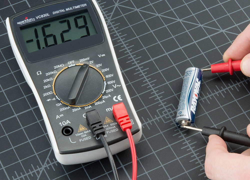
By adhering to these measures, you can assess the circuit for both safety and performance. It is imperative that you take proper security precautions while testing the circuit and abide by the manufacturer's recommendations for secure operation. Modify the circuitry accordingly if you identify any problems to guarantee safe yet efficient functioning.

Choosing the Right Type of Battery for Flashlight Circuit

Different types of Battery Types

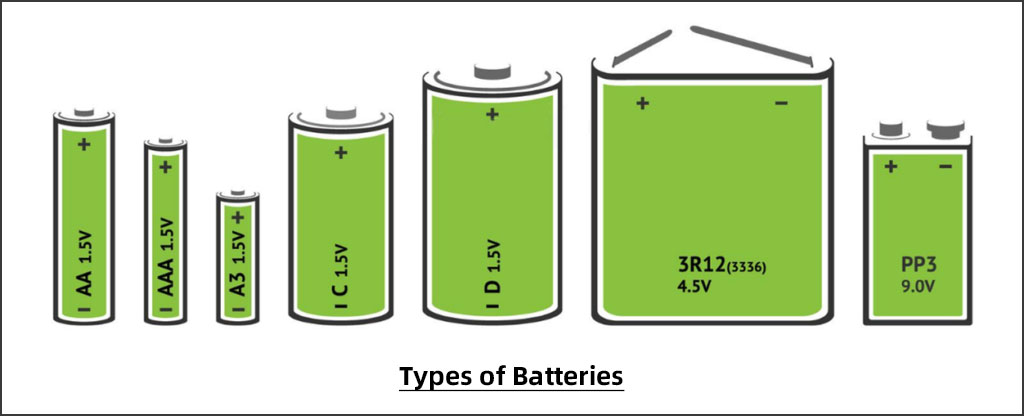
Selecting the ideal battery for your LED flashlight is absolutely essential in order to guarantee optimal and reliable performance. While choosing the right type of battery, keep these key factors in mind:

  • Voltage: To ensure optimal performance, the voltage of your battery must correspond with that required by both the LED and inverter IC. If it's insufficient, the light may not turn on; if too much electricity is present, it can ruin your LED altogether.
  • Capacity: The capacity of the battery determines the runtime of the LED flashlight. A higher-capacity battery will provide longer runtime, but it may be larger and heavier.
  • Size: The size of the battery should be small enough to fit in the LED flashlight but large enough to provide sufficient power.
  • Chemistry: Different battery chemistries like Alkaline, NiMH, Lithium-ion, etc. have different performance characteristics like voltage, capacity, weight, and cost. The battery chemistry should be selected based on the specific requirements of the LED flashlight.
  • Cost: The cost of the battery should be considered when selecting a battery for the LED flashlight. A higher-capacity battery or a battery with better chemistry may be more expensive.

By considering these factors, you can choose the right type of battery for the LED flashlight that provides efficient and reliable performance at an affordable cost.

Troubleshooting on Flashlight Circuit

If you encounter any issues with the LED flashlight circuit with an inverter IC, the following troubleshooting steps can be followed to identify and rectify the problem:

  • Check for Loose Connections: Check all the connections in the circuit to ensure that they are securely connected. Loose connections can cause a disruption in the flow of current and may lead to a malfunction.
  • Check the Battery: Check the battery voltage using a multimeter to ensure that it is fully charged and within the expected range.
  • Check the LED: Test the LED by connecting it to a known good power source to ensure that it is working correctly. If the LED is not lighting up, it may be damaged or connected incorrectly.
  • Check the Inverter IC: Ensure that the inverter IC is connected correctly and that it is receiving power. Use a multimeter to check the output voltage of the inverter IC.
  • Check for Short Circuits: Use a multimeter to check for any short circuits in the circuit. Ensure that the voltage levels are within the expected range.
  • Check for Overheating: Monitor the circuit while it is in operation for any signs of overheating. Overheating may be an indication of a short circuit or excessive current flow.

By following these steps, you can identify and rectify any issues with the LED flashlight circuit with an inverter IC. If the issue cannot be resolved, consult a professional or seek assistance from the manufacturer.

Conclusion

In conclusion, building an LED flashlight circuit with an inverter IC requires a good understanding of the components and the design process. By selecting the correct type of inverter IC, designing the circuit diagram, soldering the components onto a PCB, testing the circuit for functionality and safety, and choosing the right type of battery, you can build an efficient and reliable LED flashlight. If any issues arise, following the steps detailed above will help to quickly identify and rectify any problems with the circuit. Overall, building an LED flashlight circuit with an inverter IC can be a fun and rewarding project for electronics enthusiasts and DIY hobbyists alike.

Tag: Flashlight Circuit
  • PCB
    Prototype
  • PCB
    Assembly
  • SMD
    Stencil

Dimensions: (mm)

×

Quantity: (pcs)

5
5
10
15
20
25
30
40
50
75
100
120
150
200
250
300
350
400
450
500
600
700
800
900
1000
1500
2000
2500
3000
3500
4000
4500
5000
5500
6000
6500
7000
7500
8000
9000
10000

Other Quantities:(quantity*length*width is greater than 10㎡)

OK

Layers:

Thickness:

Quote now