
 PCB Assembly
 Layer Buildup
 Online Tools
 PCB Design-Aid & Layout
 Mechanics
 SMD-Stencils
 Quality
 Drills & Throughplating
 Factory & Certificate
 PCB Assembly Factory Show
Certificate
PCB Assembly Factory Show
Certificate
Support Team
Feedback:
support@nextpcb.com


The start/Stop Circuit is a very helpful Ladder Logic Programming Pattern. This design is a continuation of the State Coil and an extension of the Sealed Coil design. The Start/Stop Circuit is "stop dominant," in contrast to the State Coil, which is "trigger dominant" (i.e., the Trigger condition takes precedence over the Break Condition):
When the PLC is turned off, or the ladder logic program is reset, the Run coil returns to a de-energized (off) state, much like the Sealed in Coil does. This is a helpful attribute because, when the machine first starts up, we probably want the motors and other components to be in the off state until the logic decides to turn them on.
In this article,
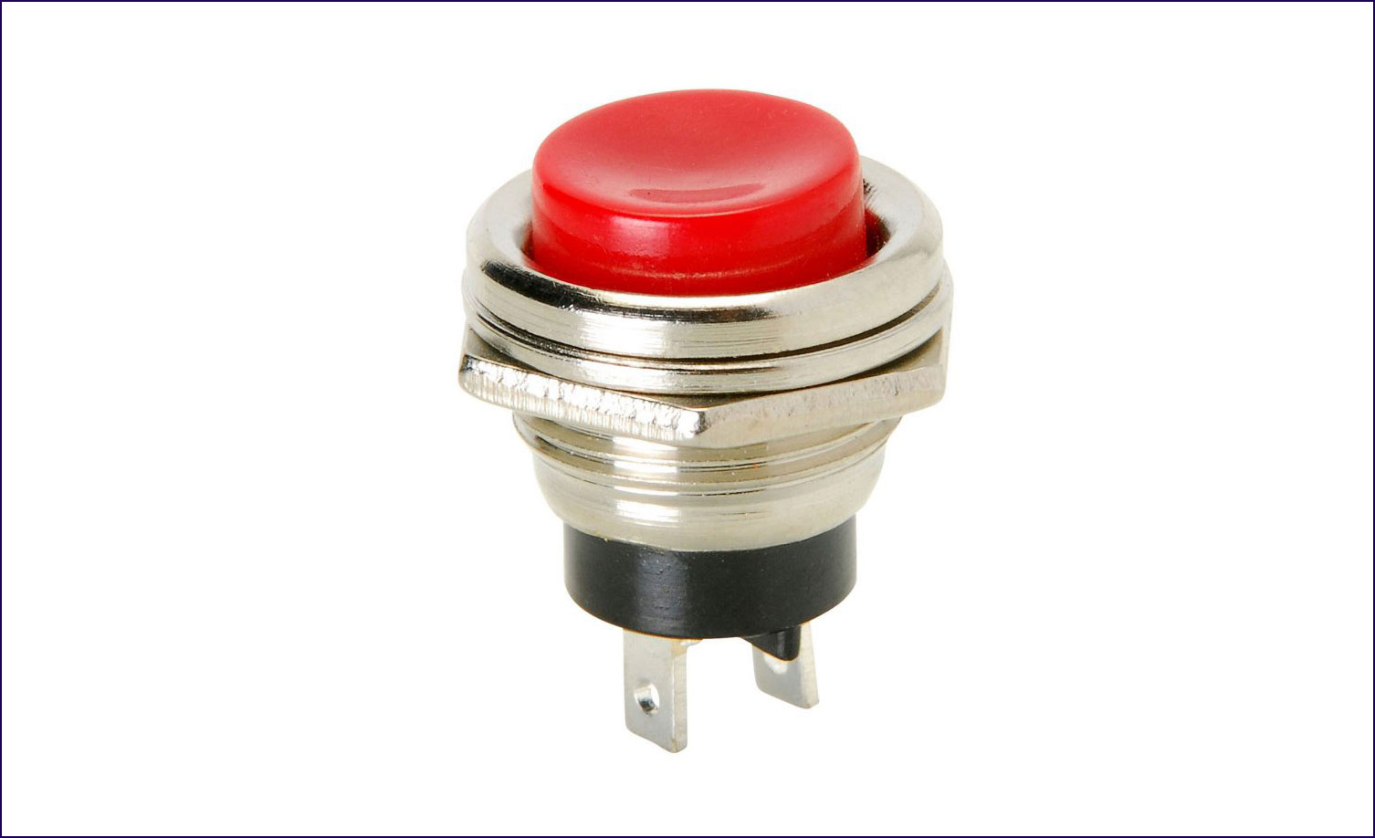
A circuit with a built-in single push button for turning on or off electrical devices, such as equipment or motors, is recognizable as a start-stop circuit. In addition to overloads and contacts, these electrical circuits also include relays or contactors. They are frequently identifiable in machinery, such as control circuits on conveyor belts. A control circuit often decides when a component or motor should start and stop operating.
A start-stop circuit follows a variety of distinct parts. We will go over each requirement for each component in the circuit below:
In a start-stop circuit, the push buttons and contacts turn the circuit on and shut it off. By means of pushbuttons or switches, they are to "start" and "stop" the electrical circuit.
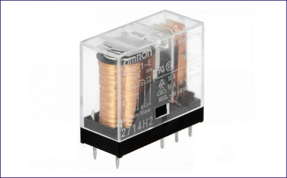
Electric or electromagnetic switches, relays, and contactors can close or open circuits in response to a specific stimulus. Contractors, on the other hand, are unique relays; relays are not contractors.
Relays are essential for switching lesser currents drawing courses, but contactors are appropriate for bigger current circuits.
In order to close the circuit, contractors must first energize or close their coils because they are normally open (NO). Relays have two possible states: normally open (NO) and normally closed (NC). As a result, switching on the relay coils transforms a NO circuit into an NC and an NC circuit into a NO. Relays use the amplification effect to regulate larger circuits. You apply a portion of the line voltage to its coils to activate them and manage higher-voltage systems.
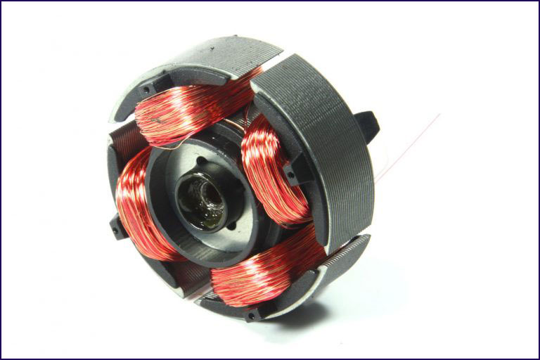
Motors are commonly identifiable in start-stop control circuits. Conveyor belts and process machinery that require movement must have start-stop control.
Electric motors are a sort of machinery that use electromagnetic phenomena to transform electrical energy into mechanical energy.
The interaction of conductors carrying current in a direction that is at right angles to a magnetic field is how most electric motors produce their mechanical torque. The arrangement of the conductors and the magnetic field and the degree of control that exerts over the mechanical output torque, speed, and position vary between the many types of electric motors.
Standardized motors provide industrial users with convenient mechanical power. The largest, with outputs exceeding 100 megawatts, are for ship propulsion, pipeline compression, and pumped-storage applications.
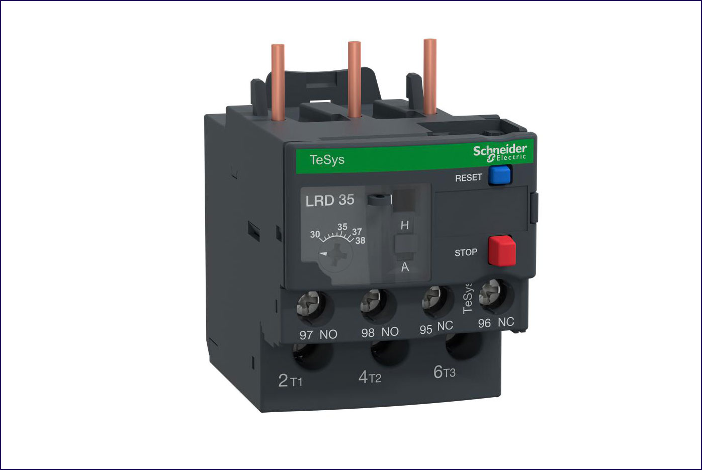
Overload relays are protective relays that open an electrical circuit in the event of a thermal, power, or electrical overload.
Typically they follow the normally closed condition as the initial condition(NO), which means they will only be operational if there is an overload.
Furthermore, the ratings and applications of overload relays vary. As a result, before installing a relay, check its rating to protect your motors and other accessories.
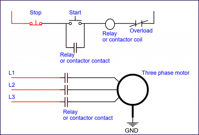
Most control circuits employ 24V DC as the control voltage. The voltage level is determined by how you control your start-stop circuit as well as how the components in the circuit are configured. If you use a start-stop circuit to control a 24V contactor coil, you can keep the motor's supply voltage separate from the control voltage. This keeps your control voltage low, and if you have a three-phase motor connected, the supply is simply terminated into the contactor (which would be controlled by your 24V start-stop). The 24V coil controlled by your start-stop circuit would then tell the contactor when to turn on your motor.
You can connect this directly to your motor or component if you use higher-rated contacts. Some systems employ 240v contacts capable of directly controlling a single-phase motor.
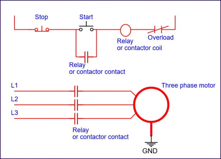
A start-stop circuit is powered by relays, buttons, motors, and overload relays.
To help you understand, the black lines represent components that lack power, and the blue bars represent components that are passionate.
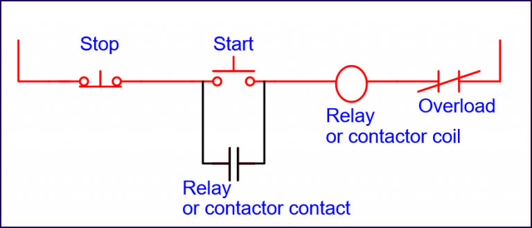
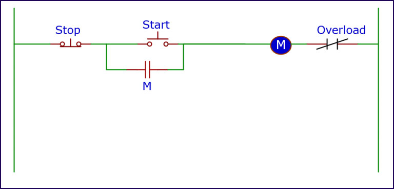
The start-stop circuit is shown in its OFF state. In this state, the normally closed stop button is closed while the normally open start button is open. The current flow path of the start-stop circuit is shown by the red highlighted area. A control circuit's voltage rating typically ranges from 24V to 400V. In this situation, 24V is required for the control functions.
The motor is decoupled from the power source, and the relay/contactor coil is in this state.
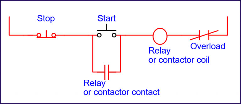
The moment you press the start button, the current will flow through. The relay or contactor coil then transitions to an active state. A contractor offers the ability to regulate motors. The motor can run when the contactor is stimulated, which sends current. After the relay or contactor coil energizes, the contact becomes powered up. As a result, the circuit closes, allowing you to release the button while the current continues to flow. Otherwise, the course is fully operational until you hit the stop button or a fault happens.
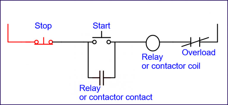
As mentioned, pressing the stop button—also known as the closed position—stops the circuit's current flow. The course then opens as a result of the coil losing power. Also, by pressing the start button, you can restore the circuit's functionality.
There are two ways to control the wiring of the start-stop circuit: two-wire control and three-wire control.
A control device having contacts on it called a two-wire control has the ability to either activate or deactivate the pilot device. Smaller loads that rely on fewer connections must also run at low current levels in order to avoid damaging the circuit. Two-wire controllers can therefore be used to control motors or lights. For this configuration, releasing the button opens the coil, implementing closed contact to guarantee operation.
A starter coil in series with a contact pilot device is used as a 2-wire control for a start-stop circuit. A pressure or limit switch is the type of contact pilot device used most frequently.
When the circuit must function without outside assistance, we employ it. The relays automatically turn on if there is a power outage while the switches' contacts are undergoing closed condition. So, when the electricity is restored, the circuit is finished. In the 2-wire control, the starter and pilot device are connected by just two wires.
The start/stop control position circuit illustrates a three-wire control circuit. For the most part, it depends on quick contact, start/stop stations, and a seal that opens upon contact. Parallel connections between this contact and the start button allow it to regulate the voltage applied to the coil. This setup has different functionality than the two-way control circuit since it has fewer components.
Three wires are essential in a 3-wire circuit to link the starter and the pilot device. The starter coils get "started" or "activated" using momentary switches.
As a result, they need outside stimulation to close the circuit, like briefly hitting a start button. Parallel a secondary starter circuit to the start button. As soon as you remove the start button, be sure the powering up the motor.
(The circuit goes to the de-energized condition in the event of a power outage. Hence, the start button must be momentarily pressed to restart closing the course).
When you press the start button, current flows through the push button and seal-in contact. The contact then manages coil power distribution. As a result, you can depress the start button without disrupting the current flow. When you press the start button, current flows through the push button switch and the seal-in contact. The contact then manages coil power distribution. As a result, you can depress the push button switch without disrupting the current flow. Various methods are possible to use to de-energize the motor's coil. When the motor overloads, the contacts open. Pressing the stop button prevents power from reaching the seal-in contact, resulting in a de-energized coil.
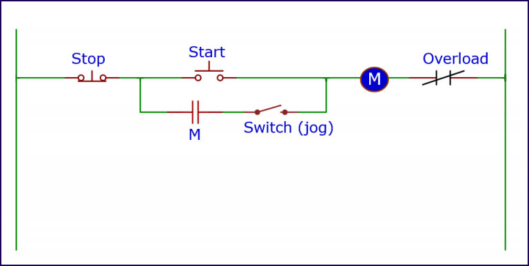
Another method for closing the control circuit is to place the switch in the jog position. As a result, the lock is undergoing de-energizing. As a result, the device will no longer receive power from the seal-in contact. To re-energize the coil, you must press the start button.
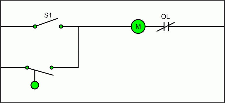
As you can see, the motor starts up whenever current passes through a contactor coil
Workers in industry and automotive should be as safe as possible, especially when dealing with specific systems. As a result, understanding a control system and how it works can result in a safe ride. As a result, specific processes can start and stop at any time by pressing a single push button. Control circuits in machinery will become more accessible as automation tasks advance. As a result, it's a good idea to make the best use of automated systems possible.
Still, need help? Contact Us: support@nextpcb.com
Need a PCB or PCBA quote? Quote now


 Printed Circuit Boards
 Surface

