NextPCB Capabilities
Printed Circuit Boards
NextPCB Capabilities
Printed Circuit Boards
 PCB Assembly
 Layer Buildup
 SMD-Stencils
 PCB Design-Aid & Layout
 Mechanics
 Quality
 Drills & Throughplating
 Factory & Certificate
 PCB Assembly Factory Show
Certificate
PCB Assembly Factory Show
Certificate
Support Team
Feedback:
support@nextpcb.com


Introduction
The demand for a simple, reliable communication protocol, especially for linking devices inside the limited dimensions of modern electronics, is where the history of I2C starts. This requirement was met by the protocol's development, which was led by Philips (now NXP Semiconductors) in the early 1980s and ultimately helped I2C gain popularity.
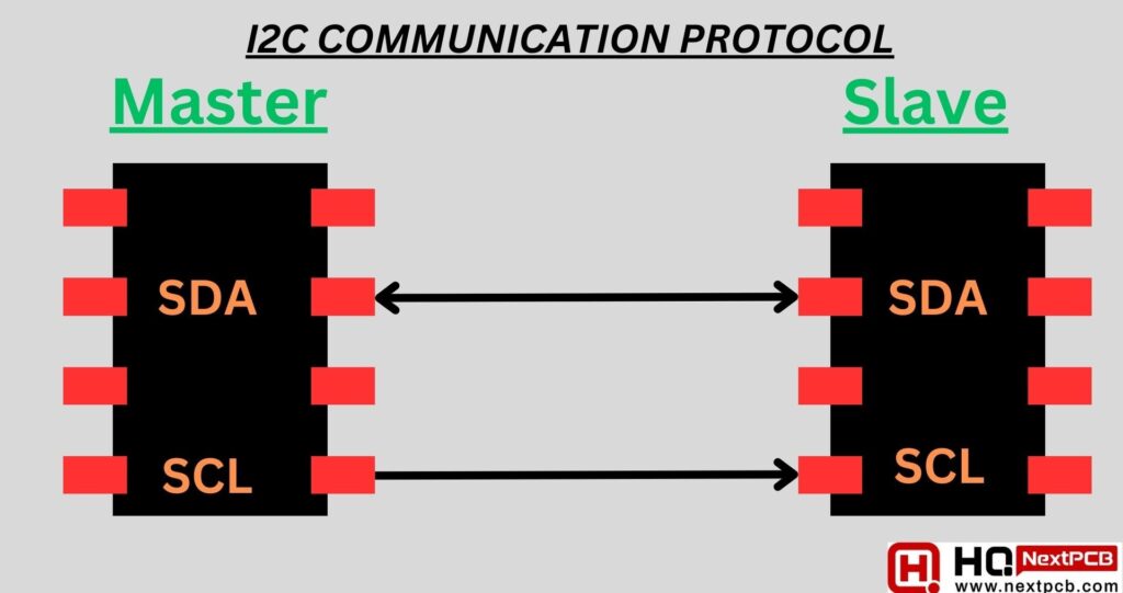
What is I2C protocol - The adaptable and extensively used serial communication protocol known as "Inter-Integrated Circuit," or I2C for short, is the fundamental basis of data interchange between integrated circuits, sensors, and other electronic components. Because it uses only two wires — the Serial Data Line (SDA) and the Serial Clock Line (SCL) — to enable effective, synchronized communication between devices, it is widely used in the electronics industry.
The Serial Data Line (SDA) and Serial Clock Line (SCL) comprise the two-wire i2c interface that defines the I2C protocol. It makes inter-integrated circuit communication smoother. This article examines the read/write bit, which is an essential part of electric circuits used for data interchange, with an emphasis on the protocol's physics. It also emphasizes how crucial addressing is to ensuring proper data transport.
Learning about the workings of the I2C (Inter-Integrated Circuit) communication protocol is essential for anyone engaged in embedded systems or electronics. Multiple devices can interact over just two wires thanks to the flexible and widely used I2C serial communication standard: the Serial Data Line (SDA) and the Serial Clock Line (SCL). We will explore the inner workings of I2C or how I2C works in this section, clarifying how devices synchronize, how does i2c work, communicate, and exchange data without any problems.
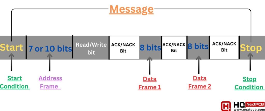
Start and Stop Conditions:
I2C starts and ends 12c communication with special conditions: Start and Stop. Start Condition happens when SDA is changed from high to low while SCL is high. Stop Condition is SDA goes from low to high while keeping the SCL high.
Addressing:
I2C employs 7 or 10-bit addresses for device identification, enabling 128 or 1024 unique addresses,10/2 wire amps. Devices are chosen by their unique address during the Start condition, allowing multiple devices on the i2c data bus to respond when addressed.
Read and Write Bits:
In I2C, the Read/Write bit after device addressing distinguishes data flow: '0' means write (master to slave), '1' means read (slave to master), determining data direction.
Data Transmission:
I2C sends data in 8-bit bytes, starting with the MSB. After each byte, an ACK bit confirms successful receipt. No ACK indicates a problem and may end transmission.
Addressing in the I2C protocol is fundamental, identifying and selecting devices for data communication. It establishes connections between master and slave devices, enabling data exchange. I2C addressing employs 7-bit or 10-bit device addresses. A 7-bit address offers 128 unique device addresses, while a 10-bit address extends to 1024. These distinctions are crucial when multiple devices share the same I2C bus.
In I2C, the master starts communication with a transmitted Start condition and the 7-bit device address of the target slave. This unique address ensures accurate recipient selection, trigger on oscilloscope, with the MSB sent first, followed by the remaining six bits, i2c seven segment display. Address transmission in I2C also sets the Read/Write bit, indicating data flow. '0' means write (master to slave), while '1' means read (master receives from slave).
After sending the address byte, the addressed device acknowledges by pulling SDA low for one clock cycle. No acknowledgment may suggest device absence or unresponsiveness, requiring troubleshooting.
In order to control data direction, the I2C protocol uses the Read/Write bit. Enabling master-slave data synchronization, it is the ninth bit following the 7-bit device address. When '0,' it denotes a write operation, in which configuration settings, commands, or operational data are sent from the master to the slave.
On the other hand, a read operation is indicated by '1' in the Read/Write bit. The addressed slave is supposed to provide data to the master, such as sensor readings or status updates for processing.
In an I2C transaction, the seemingly straightforward Read/Write bit is crucial for proper data transfer. It is essential to the data exchange process's successful i2c communication between the slave and master devices.
The first 8-bit data frame is ready to be transmitted after the master detects the acknowledgment (ACK) bit from the slave. This frame is organized regularly, starting with the most important section each time. Every data frame transmission is followed immediately by the crucial ACK/NACK bit, which guarantees the frame's successful reception.
Before moving on to the next data frame, the master or slave, depending on which data sender, must verify receipt with the ACK bit. When every data frame has been sent, the master can initiate a stop condition to end the transmission. This means that the Serial Clock Line (SCL) will undergo matching voltage transitions before the Serial Data Line (SDA) undergoes a particular voltage transition, ending with the SCL line staying high.
The Inter-Integrated Circuit (i2c communication protocol) is known for its precise and synchronous data transmission. To understand how data is transferred between devices using I2C, it's essential to grasp the sequential steps that govern the process. Here, we outline the key steps involved in I2C data transmission:
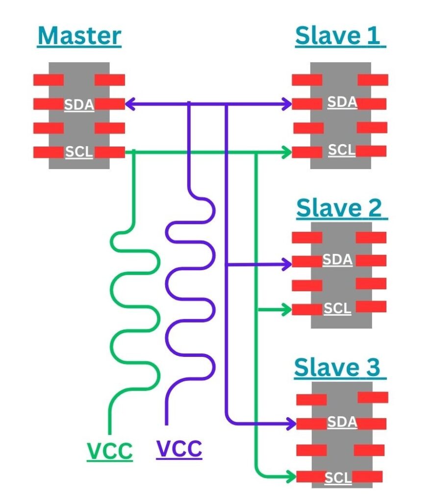
In the I2C Communication Protocol, a common configuration is a single master communicating with multiple slaves on the same bus, known as "single master with multiple slaves." This setup offers benefits and challenges. The master controls communication, addressing each slave individually, managing data flow, and acknowledgments.
The addressing feature of I2C makes it possible to manage several slaves from a single master. 128 (2^7) distinct addresses are possible when using a 7-bit address. Using 10-bit addresses offers an increased range of 1,024 (2^10) distinct addresses, however it is less popular. In order to link several slaves to a single master, 4.7K Ohm pull-up resistors must be included in the wire arrangement. The power supply voltage (Vcc) is connected to the Serial Data Line (SDA) and Serial Clock Line (SCL) using these resistors. This configuration enables smooth communication across the I2C network.
Challenges include sequential communication by the single master with multiple slaves, potentially causing latency, especially with multiple frequent exchanges. Collision avoidance mechanisms, electric clock mechanism, like arbitration, are crucial to prevent i to c conflicts when multiple slaves respond simultaneously.
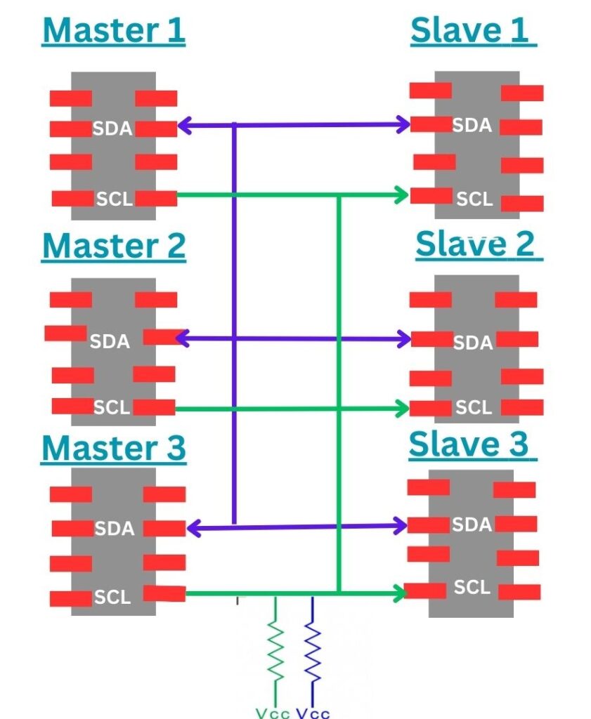
The "multiple masters with multiple slaves" setup in the I2C Communication Protocol is highly flexible and complicated. With several masters and slaves on a single bus, it enables separate subsystem or module communication. When numerous masters request access at the same time, the primary problem is bus arbitration. One master at a time is granted access by a method that resolves disputes and is frequently based on priorities or collision-avoidance techniques.
Addressing becomes complex in this system because masters must be programmed to identify target slaves accurately and avoid communication conflicts.
Although complex, the multiple masters with multiple slaves setup offers extensive connectivity and independent data exchange, 28 fundamentals of sda. It's crucial for advanced systems like embedded systems, sensor networks, and scenarios involving different control or processing units to understand how multiple masters with multiple slaves coexist on the same I2C bus, aiding system design and maintenance.
The I2C (Inter-Integrated Circuit) communication protocol offers several advantages that have contributed to its widespread adoption in the world of electronics. These advantages make I2C a preferred choice for interconnecting integrated circuits and electronic components. Here are the key benefits of the i2c protocol explained:
While the I2C (Inter-Integrated Circuit) communication protocol i2c offers numerous advantages, it is not without its limitations. Here are some of the key disadvantages of the I2C protocol :
In conclusion, the I2C (Inter-Integrated Circuit) - Communication Protocol is a powerful and widely adopted standard in the field of electronics. Its simplicity, versatility, and support for various configurations, such as SCL and SDA. This article has valuable instructions for connecting and coordinating integrated circuits and electronic components.
While I2C offers several advantages, including synchronized data exchange and efficient communication, It also comes with limitations, such as clock speed constraints and susceptibility to noise. what does scl mean or what does scl stand for - SCL stands for "Serial Clock Line". Understanding these strengths and weaknesses is essential for effectively leveraging in what is 12c or how I2C works in diverse applications, where reliable and precise data transfer is paramount.
- Serial Communication Protocols
- Free PCB Assembly Offer is Now Live: Experience Reliable PCB Assembly from HQ NextPCB
- Autumn Offer: Get $30 off PCB orders over $100 with NextPCB
- HQ NextPCB Introduces New PCB Gerber Viewer: HQDFM Online Lite Edition
Still, need help? Contact Us: support@nextpcb.com
Need a PCB or PCBA quote? Quote now


 Surface