
 Surface


Stacy Lu

 NextPCB Capabilities
Printed Circuit Boards
NextPCB Capabilities
Printed Circuit Boards
 PCB Assembly
 Layer Buildup
 SMD-Stencils
 PCB Design-Aid & Layout
 Mechanics
 Quality
 Drills & Throughplating
 Factory & Certificate
 PCB Assembly Factory Show
Certificate
PCB Assembly Factory Show
Certificate
Support Team
Feedback:
support@nextpcb.com


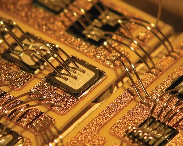
Wire bonding is the process of connecting the internal circuitry of a semiconductor chip to the outside world — the pins, pads, or leads that let the chip communicate with the rest of a PCB or assembly. It is the dominant interconnection method in modern electronics, with an estimated 4 trillion wire bonds formed every year, and it remains the standard choice wherever a durable, cost-effective, and reworkable connection is needed between a die and its package or substrate.
This guide covers how wire bonding works, where it's used, the three main bonding methods, the materials involved, and the design rules that keep bonds reliable in production.
Semiconductor manufacturers use wire bonding to connect integrated circuits to the electrical systems around them. It is the preferred technique for linking a die to a package, or for linking one PCB to another, largely because of its balance of cost and durability — wire bonding is, at its core, a welding process that uses heat, pressure, and/or ultrasonic energy to fix fine metal wires to a chip's bond pads.
Forming reliable, precise connections between a semiconductor die and its package (or between PCBs) is a demanding process. Every bond needs to be accurate and repeatable at scale, because a single weak or inconsistent connection can lead to field failures with real economic consequences — which is why manufacturers continue to invest in refining wire bonding processes rather than reverting to older techniques.
Early alternatives, such as attaching wire to a silicon die using small solder balls, proved unreliable in practice. Solder joints were often mechanically weak, and in some cases the solder could interact with the semiconductor material itself, degrading device performance. Wire bonding largely displaced these methods for exactly this reason.
Wire bonding shows up in most of the electronics we use daily — smartphones, laptops, and other high-density devices built around microcontrollers and microcomputers. It is favored in these applications because it delivers durable, functional interconnects at a manageable cost.
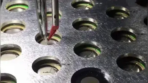
In mobile phones, wire bonding is commonly found inside the battery pack, where ultrasonic metal-to-metal bonding joins individual cells together. This replaced the older practice of spot welding, which tended to introduce reliability problems: localized high temperatures at the weld point could shorten battery lifespan, and loose connections from inconsistent spot welds could damage the battery management system (BMS). Wire bonding has largely displaced spot welding across the industry for these reasons.
Several methods exist for connecting cylindrical battery cells to a busbar, including wire bonding, laser welding, resistance welding, and spot welding. In wire bonding, ultrasonic energy causes the wire (or ribbon) to share electrons with the target surface, forming an atomic bond. The ultrasonic process strips away the natural oxide layer on the metal, exposing fresh aluminum and allowing valence electrons to transfer freely — which is part of what makes wire bonding well suited to EV battery assembly.
Wire bonding also plays a critical role in microcomputers and microcontrollers, where precise, durable terminal connections directly affect device performance. Because signal integrity is central to how these devices function, the choice of wire material for these bonds has a measurable effect on the finished product's reliability.
As PCB manufacturing trends toward higher sensitivity and density, wire bonding has become an increasingly common requirement across the PCB industry. Compared with older interconnection methods, wire bonding offers several concrete advantages:
Taken together, wire bonding's main advantages are its corrosion resistance and long-term connection stability. In EV battery applications specifically, wire bonding provides low-resistance, mechanically robust connections that help maintain continuous power delivery from the pack.
At its core, wire bonding exists to create reliable, durable connections between a chip and the components or circuits around it. It's particularly well suited to applications operating above GHz-range frequencies, where signal and voltage pulse integrity are critical — a growing requirement as more of the electronics industry moves toward high-speed digital and real-time communication between modules.
Because modern devices increasingly depend on fast, low-distortion signal transfer between components, PCB manufacturers need an interconnection method that can keep up. Wire bonding fits that requirement well, which is a large part of why it remains the default choice across the industry today.
In EV manufacturing specifically, a few properties of wire bonding matter most to engineering teams:
Wire bonding supports in-situ mechanical pull testing: a preset, non-destructive force is applied to a bond to verify its strength. This can catch weak or non-stick bonds — a common cause of early-life ("infant mortality") failures — before a unit ships. Pull test results are captured immediately and can feed into a traceability database alongside the rest of the bonding process data.
Stress relief loops between connection points help absorb thermal strain from both the environment and the product itself. Wire diameters used in bonding range from roughly 18 microns up to 600 microns, allowing engineers to select a diameter that meets resistance and conductivity requirements. Loop geometry can also be adjusted to fine-tune resistivity or impedance matching on a per-connection basis. Ribbon bonding, which uses a larger cross-section than round wire, is commonly used where higher current-carrying capacity is needed.
Modern wire bonders record electrical and mechanical signals in real time during the bonding operation, allowing bond quality to be assessed while the process is still running. Data analysis techniques can flag known failure signatures — contamination or misformed bonds, for example — and flag suspect bonds for further post-bond inspection.
Unlike many alternative interconnection methods, which offer only one chance to get a connection right, wire bonding allows individual weak or failed wires to be replaced and reworked without scrapping the entire assembly. This per-wire repairability is one of wire bonding's more practical advantages in production.
Wire bonding in industry generally falls into three main categories:
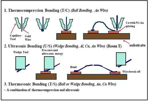
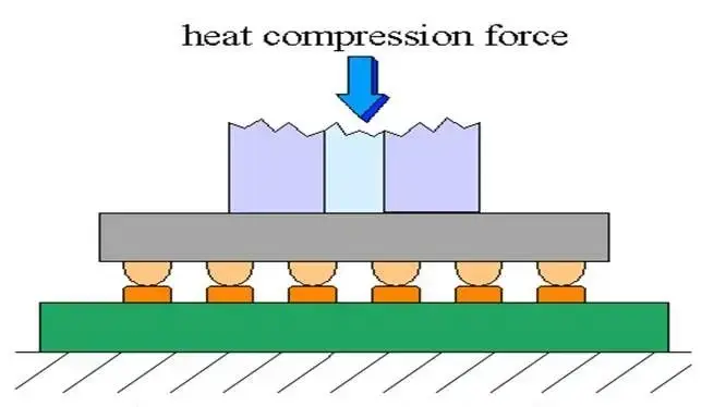
Thermocompression bonding is a solid-phase, direct-bonding process that doesn't require an intermediary layer, typically using metals such as Cu, Au, Al, or Ti to strengthen one or both bonding surfaces. The bond forms through a combination of atomic contact, heat, and pressure. It's a practical way to achieve wafer-level bonding at relatively low temperatures without needing an applied electric field (as in anodic bonding) or an involved pre-bond cleaning step. Aluminum and copper are especially favored for 3D integration work.
Sealing and electrical connection can often be achieved in a single bonding step. While gold and copper thermocompression bonding have been well established for some time, aluminum-based bonding has drawn growing interest because it can be implemented very quickly, including within CMOS process flows.
Advantages of thermocompression bonding include:
Thermosonic bonding joins two materials using a combination of pressure, time, heat, and ultrasonic energy. Typically, the wire is heated slightly before being pressed and lightly rubbed against a heated surface, usually at or below about 150 °C.
This method was originally associated with gold ball bonding, since ball bonding was the first application to combine ultrasonics with thermal bonding. The term "thermosonic bonding" is now often used more broadly to include wedge bonding as well, though some engineers still reserve it specifically for ball bonding.
Copper wire has seen growing use in this process in recent years, though it requires equipment modifications to prevent oxidation of the wire (and particularly the ball) during flame-off.
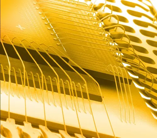
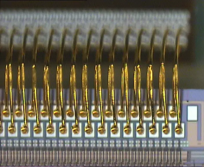
Gold wire bonding attaches a gold wire between two points in an assembly to form an electrically conductive path, using a combination of force, heat, and ultrasonic energy.
The process begins by forming a small gold ball at the tip of the capillary (the wire bonding tool). The tool presses this ball against the heated bond surface while applying ultrasonic energy, typically in the 60–120 kHz range.
Once the first bond is formed, the wire is shaped into the loop geometry required for the assembly, and a second bond — the "stitch" — is formed on the opposite surface, where the wire is pressed and then sheared off with a clamp.
Compared to some solder-based connections, gold wire bonding offers roughly an order of magnitude better electrical conductivity within a package. Gold wire is also softer than most alternatives and more resistant to oxidation, which makes it well suited to delicate bonding surfaces.
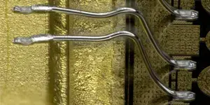
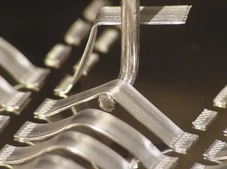
Process details vary by application. For delicate materials, a gold ball is sometimes formed on the second bond as well, creating a softer connection that won't scratch the surface. In tight layouts, a single ball can serve as the starting point for two separate bonds, forming a "V"-shaped connection. Where extra strength is needed, a ball can be placed on top of a stitch to reinforce it. Modern wire bonder software supports a wide range of these variations.
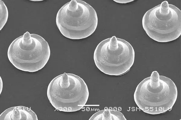
Bump bonding (or stud bumping) creates the interconnects used in flip-chip applications between a die and its substrate. It's typically performed at the wafer level, though assembly-level bumping is also possible.
The process starts much like gold ball bonding: a ball forms at the capillary and is pressed onto the surface using force, heat, and ultrasonics. Instead of forming a loop, however, the wire is sheared off immediately above the ball, leaving a flat bump on the surface.
Bump size is controlled largely by ball size, which in turn depends on maintaining a consistent wire tail length before each ball forms. Inconsistent execution here shows up directly as variation in bump sizing — and since these bumps need to be uniform across an entire wafer for downstream assembly to succeed, consistency in the shearing step is critical to bump height, shape, and planarity.
Wedge bonding forms both ends of a connection as stitches, using a wedge tool rather than a ball for the first bond. The resulting connections are narrow and elongated. Both gold and aluminum wire can be used, though aluminum at room temperature is the more common choice.
Either round wire or ribbon can be used in wedge bonding. Unlike a ball bonder's capillary, which must align with the bond direction, a wedge tool can rotate freely, allowing bonds to be formed from virtually any angle on the assembly.
Ultrasonic bonding has been in use since the 1940s, originally developed for metal welding before being adapted for plastics as well. Whether it's feasible for a given application depends largely on the thickness of the parts being joined — thick components generally cannot be bonded this way, and the maximum practical thickness (typically a few millimeters) depends on the equipment and materials involved. Ultrasonic metal welding works best with malleable metals such as nickel, copper, and aluminum, and is widely used for sheet metal, microcircuit connections, foils, ribbons, and meshes.
The process requires a clean surface, free of debris, grease, or other contaminants — even small amounts of contamination can lead to corrosion or bond failure. In battery applications, cleaning must be done carefully to avoid damaging internal components, which rules out abrasive mechanical cleaning methods. Manual cleaning with cloths, isopropanol, or acetone can produce good results, but it doesn't scale well for high-volume manufacturing. Laser cleaning is currently the most practical method for cleaning small, localized surfaces in an automated production line.
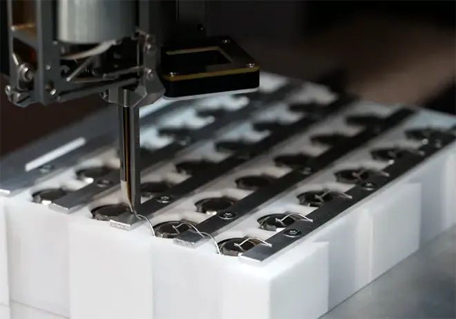
Ultrasonic bonding is widely used in the computing and electronics industry, aerospace and automotive, and medical device manufacturing. In EV battery module assembly specifically, ultrasonic wire bonding is a core technology for connecting cells to busbars (current collectors), typically located on top of the module, to distribute current.
| Wire Bonding Method | Operating Temperature | Wire Material | Pad Material | Note |
|---|---|---|---|---|
| Thermocompression | 300–500°C | Au | Al, Au | High pressure, no ultrasonic energy |
| Ultrasonic | ~25°C | Au, Al | Au, Al | Low pressure, ultrasonic energy |
| Thermosonic | 100–240°C | Au, Cu | Al, Au | Low pressure, ultrasonic energy |
Gold remains the most widely used wire bonding material, thanks to its high electrical conductivity, strong corrosion resistance, and its ability to form reliable bonds in an ambient (non-inert) environment. Bonding-grade gold wire is refined to very high purity, typically 99.99%.
Gold wire supports both ball bonds and wedge bonds. A typical gold ball bond forms in five steps:
As the industry balances competing demands for lower cost, smaller components, and greater functionality, insulated gold bonding wire is emerging as one way to help manage those trade-offs. Adding insulation to bare gold wire helps prevent short circuits, which opens up chip layouts that would otherwise be impractical.
The key difference between aluminum and gold wire bonding is temperature: aluminum bonds form using force and ultrasonic energy alone, without needing to heat the surface to the roughly 150 °C typically required for gold bonding. Beyond that, the bonding steps — including the two attachment points and loop geometry — are essentially the same as for gold wire.
Aluminum wire offers reliable electrical continuity, similar to gold, but with a few distinct advantages of its own. Because aluminum bonds don't tolerate the high temperatures gold bonding requires, aluminum wire is generally the better choice for temperature-sensitive assemblies, and it's preferred over gold on aluminum surfaces in hermetically sealed packages — the elevated temperatures needed for hermetic sealing can otherwise weaken gold-to-aluminum bonds.
Aluminum wire is the material of choice for wedge bonders, and together with gold it makes up the two dominant wire types in the industry. Other materials, including certain alloys, are used in specific niche applications where their particular properties are needed. Reliable wire bonding, regardless of material, depends on using the correct combination of frequency, force, and temperature.
Copper ball bonding to IC metallization has drawn significant industry interest recently, largely because copper is more affordable than gold and more resistant to "sweep" — lateral wire movement during plastic encapsulation. Its main drawback is bondability: because copper is harder than gold or aluminum, it can push metallization aside during bonding rather than bonding cleanly, which means a tougher metallization layer is often required. Copper also oxidizes readily, so the ball bonding process needs to be performed in an inert atmosphere.
Wire bond manufacturing and long-term reliability face a range of challenges that depend heavily on the material system, bonding parameters, and operating environment involved. Aluminum-aluminum (Al-Al), gold-aluminum (Au-Al), and copper-aluminum (Cu-Al) wire-bond/pad-metal systems each require different production conditions and behave differently even under similar operating conditions.
Ongoing research continues to evaluate different metal systems, refine key manufacturing parameters, and identify common reliability issues in wire bonding. Material choice is typically driven by the target application and use environment, weighed against electrical, mechanical, and cost considerations.
For example, a high-current device destined for space applications might call for a large-diameter aluminum wire bond inside a hermetically sealed ceramic package, avoiding gold entirely if cost is a significant constraint. Copper wire bonding for automotive applications is another area of active research — one of many ongoing efforts to determine which material systems perform best in which applications.
From a production standpoint, bonding parameters are critical to both bond formation and bond quality. Bond force, ultrasonic energy, temperature, and loop shape all significantly affect the outcome. Different bonding methods (thermosonic, ultrasonic, thermocompression) and bond types (ball, wedge) each carry their own susceptibility to manufacturing defects and reliability issues. Fine-pitch or complex designs often call for specific wire materials and sizes, and the bond pad's metallization and barrier-layer stack-up also directly influences how well the bond forms.
Common failure modes tied to poor bond quality or manufacturing defects include neck fractures at the ball bond, heel cracking on wedge bonds, pad liftoff, pad peel, overcompression, and improper intermetallic formation. Identifying these issues typically relies on a combination of destructive physical analysis (DPA), non-destructive testing, and wire bond pull or shear testing.
Because bond quality and long-term reliability are influenced by different factors, wire bond manufacturers sometimes overlook wear-out mechanisms while focusing primarily on bond quality. Understanding the intended application and use environment goes a long way toward avoiding reliability problems — elevated temperature, high humidity, and temperature cycling are among the most common causes of wire bond failure.
Excessive intermetallic compound (IMC) growth at high temperatures can create brittle fracture zones, a topic that's been studied extensively across different metal systems. This isn't a significant issue in same-metal systems like Al-Al, but it becomes relevant in mixed-metal systems. The brittle intermetallics formed in gold-aluminum bonds — sometimes called "purple plague" — are among the best-documented examples, and related diffusion issues such as Kirkendall and Horsting voiding can also cause bond failures.
High humidity and temperature can also introduce galvanic corrosion, most commonly seen in Au-Al systems, and this effect can accelerate in the presence of halides like chlorine. Peck's law is frequently used to model the temperature and humidity dependence of this type of corrosion, though it's less commonly applied to other metal systems.
Thermal cycling introduces its own risk: a mismatch in the coefficient of thermal expansion (CTE) between the epoxy molding compound (EMC), lead frame, die, die adhesive, and wire bond generates thermomechanical stress, which causes low-cycle fatigue from repeated shear or tensile strain on the bond. Various fatigue models exist to help predict wire bond life under these conditions.
In practice, a thorough understanding of the metal system and use environment is usually the single most important factor in improving wire bond reliability.
Wire bond pull and shear testing are widely used, though they're generally better suited to verifying manufacturing quality than predicting long-term reliability. Most of these tests use monotonic overstress techniques, where the key outputs are peak force and fracture location — the resulting damage comes from plasticity rather than the kind of wear-out mechanisms that would show up in real-world use.
Pull testing uses a metal hook to draw a wire upward along the z-axis. In a non-destructive test, a fixed force is applied; in a destructive test, force increases until the bond or wire fails. The failure mode observed provides insight into bond strength, and test parameters — especially pull speed and hook position — matter, since small variations can shift which failure mechanism shows up.
Pull testing works for ribbon bonds as well as wire. It's standard practice to pull at the wire's midpoint (a "mid-span pull"), though the hook can also be positioned near one end of the bond if that's the specific failure mode under investigation. When testing multiple samples, pulling at a consistent position is important for valid comparisons. Common failure modes include:
The wire snaps along its length rather than at either bond. Since both bonds remain intact, this result doesn't directly indicate bond strength, though it can still be a useful reference if the applied load resembles real-world conditions.
The heat-affected zone is the portion of wire nearest the ball, where heat disrupts (without melting) the wire's microstructure. When a pull test breaks at the HAZ, it indicates this is the weakest point in the bond.
The wire breaks at the loop's heel, indicating that this is the weakest part of the connection. If heel strength doesn't meet requirements, adjusting bonding parameters — bond head force or loop shape, for example — is usually the fix.
The bond separates at the neck or heel due to poor intermetallic formation. This result reflects bond strength directly, and whether it meets the application's requirements depends on the specific use case.
The bond pad itself lifts off the substrate or package during testing — a sign that the bond is stronger than the pad attachment underneath it.
Shear testing applies lateral force to a ball bond to measure how much force is needed to move it — this force represents the ball bond's strength. The two key test parameters are test speed (how quickly the load is applied) and shear height (how high above the surface the tool contacts the ball). Bond failure is the most significant outcome the test can reveal, though other failure modes are also informative; weaker bonds often trace back to material quality, contamination, or improper bonding parameters. Shear testing applies to gold and copper balls, solder bumps, and copper pillars alike.
Peel testing is generally the preferred method for evaluating ribbon connections. One end of the ribbon or wire is held with tweezers and pulled upward along the z-axis, producing a force-versus-displacement curve that reflects connector strength. Because it accommodates a wide range of ribbon sizes and loop geometries, peel testing is a flexible option for ribbon evaluation specifically.
Thermal testing exposes a wire-bonded die assembly to elevated temperature or thermal cycling to verify it can withstand application-level thermal stress, whether from normal use or from fabrication steps like encapsulation curing.
Optical or SEM inspection of wire bond structures can catch issues that other tests might miss — metallization lift-off, ball or bump deformation, soft metallization, poor heel stick, or heel cracking. Combined visual inspection during bonding also helps identify recurring problems early enough to correct them before they affect bond strength across a production run.
Because wire bonding design rules govern whether a layout is even manufacturable, they're worth calling out as their own topic rather than an afterthought. A handful of rules consistently separate a reliable wire-bonded design from one prone to field failures:
Bonding directly between two integrated circuits should generally be avoided unless the application specifically requires it. The stitching process transfers mechanical energy into the pad surface, which can crack the material beneath or within the pad metallization — a potential reliability risk. Designing in intermediate bonding pads on the substrate, rather than bonding chip-to-chip, avoids this problem.
Bond wires should never cross over another die, wire, or bond pad. An unsupported wire loop can sag under mechanical stress and contact a wire running beneath it, creating a short circuit that can damage the entire assembly.
Bond pads should be laid out to keep wire bonds as short as practical — wire length directly affects impedance, inductance, and parasitic capacitance, and unnecessarily long bonds can hurt package performance. This is worth double-checking against a given IC manufacturer's implementation notes, since some manufacturers avoid wedge bonding specifically because of the mechanical force it places on the die during production.
Vias should be kept at least 0.005 mm from the edge of a bond pad; a bond formed too close to a substrate discontinuity risks mechanical damage from the bonding energy. On multilayer substrates, keeping bond pads at least 10 mm from the conductor edge leaves enough tolerance for registration and printing variation during the bonding process.
Wire bonding connects a semiconductor die's internal circuitry to the outside world — a package, PCB, or another chip — using fine gold, aluminum, or copper wire. It's the most common interconnection method in microelectronics, used in everything from smartphones and EV battery packs to medical devices and aerospace hardware.
The three main methods are thermocompression bonding (heat and pressure, no ultrasonics), thermosonic bonding (heat, pressure, and ultrasonics, most commonly used for gold ball bonding), and ultrasonic bonding (pressure and ultrasonics at room temperature, common for aluminum wedge bonds).
Gold, aluminum, and copper are the three primary wire bonding materials. Gold offers the best corrosion resistance and can bond at ambient conditions; aluminum doesn't require heating the bond surface and suits temperature-sensitive assemblies; copper is more affordable and sweep-resistant but harder to bond reliably and prone to oxidation.
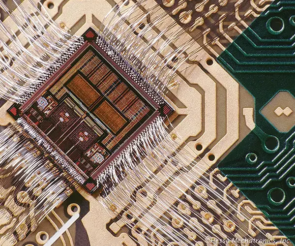
Wire bonding connects a die to its package using individual wire loops routed from the die's edge to surrounding bond pads. Flip-chip bonding instead flips the die face-down and connects it directly to the substrate through an array of solder bumps across its surface, which generally allows for a smaller footprint and shorter electrical paths, at higher process cost.
The most common tests are wire pull testing (pulling the wire until it fails, to assess bond strength) and ball shear testing (applying lateral force to a ball bond). Thermal testing, peel testing for ribbon bonds, and microscopic inspection are also used to catch defects that mechanical tests alone might miss.
Wire bonding remains the primary way electrical connections are made and, when needed, reworked at the chip level. Three bonding technologies dominate the industry: thermocompression bonding (TC), ultrasonic wedge-wedge bonding (US), and thermosonic bonding, each suited to different material systems and application requirements.
Wire bonding's popularity in microelectronics comes down to a straightforward value proposition: it delivers high-quality, high-integrity signal paths at a manageable cost, which is why it's remained the dominant interconnection method even as newer techniques have emerged. Gold, aluminum, and copper are the three materials used most widely — with gold seeing the highest overall usage, largely due to its corrosion resistance and reliability in ambient bonding conditions. Aluminum, copper, and combinations such as gold wire on aluminum metallization (or copper wire on silver metallization) are chosen depending on the specific technique and application. Ball bonding, which combines thermal energy, ultrasonic vibration, and mechanical bonding force, is the most widely used method overall, typically operating between 100 °C and 250 °C — the addition of ultrasonic vibration to conventional thermal bonding allowed the process to run faster and at lower temperatures than earlier techniques while improving joint quality.
Most industries favor wire bonding because it improves interconnect reliability while reducing overall size — a priority in robotics, sensor development, and medical device design, where equipment footprint is often a hard design constraint. This is part of why PCB manufacturers continue to push for smaller chips and components generally. Medical imaging equipment, such as laryngoscopes, is one example of a space-constrained application that relies on wire bonding to minimize size.
If your design involves wire-bonded components, chip-scale packages, or other high-density assemblies, NextPCB's engineering and PCB assembly service team can help review your design for manufacturability before it goes into production.

Still, need help? Contact Us: support@nextpcb.com
Need a PCB or PCBA quote? Quote now

