
Support Team
Feedback:
support@nextpcb.comMetal-core PCB (MCPCB) consists of a circuit layer (copper layer), a dielectric layer (insulating layer), and a substrate layer (metal base layer). Metal-core PCB means that the base layer is metal, not the standard base such as FR4 or CEM1-3. It includes the aluminum-based PCB, copper-based PCB, and iron-based PCB.
The metals most commonly used by MCPCB manufacturers and PCB designers are aluminum, copper, and steel alloys. Aluminum has excellent heat transfer and heat dissipation capabilities, but with low price, copper has better performance but is relatively more expensive than aluminum. Steel can be divided into ordinary steel and stainless steel, it is harder than aluminum and copper, but its thermal conductivity is lower than them. People can choose the proper core materials for different applications in the PCB prototype and PCB assembly.

When it comes to material classification, the subsets include:
Aluminum PCB
The aluminum PCB is a trilayer construct with:
As for pricing, it is contingent on the LED PCB specifications:
Copper Core Printed Circuit Board
A copper core printed circuit board is composed of a copper substrate, insulating layer, and the printed circuit layer. It is typically made by overlaying an insulating resin and copper foil on a copper substrate material and then undergoing a hot pressing process. Depending on the requirements and manufacturing processes, there can also be immersion gold copper substrates, silver-plated copper substrates, tin-sprayed copper substrates, and anti-oxidation copper substrates.
The copper substrate is the best for heat dissipation and also the most expensive among metal-based PCBs, generally available as single-sided and double-sided copper substrates, as well as pseudo double-sided copper substrates. The specific advantages of the copper substrate make it widely used in regions with large high and low-temperature fluctuations, precision communication equipment, and the LED car light market.
Regular Copper Core PCBs
Pseudo double-sided copper substrates generally refer to customer designs with two layers of circuits that are not interconnected, whereas real double-sided copper substrates have vias connecting the circuits on both sides.
The circuit layer of the copper substrate requires a large current carrying capacity, thus thicker copper foil is used, generally ranging from 35μm to 280μm; the thermal insulating layer is at the core of copper substrate technology, with the core thermal components being alumina and silicon powder compositions, and a polymer filled with epoxy resin, offering low thermal resistance (0.15), excellent viscoelastic properties, and resistance to thermal aging, capable of withstanding mechanical and thermal stress.
The metal base layer of the copper substrate is the support component of the substrate, requiring high thermal conductivity, and is suitable for conventional mechanical processing such as drilling, punching, and cutting.
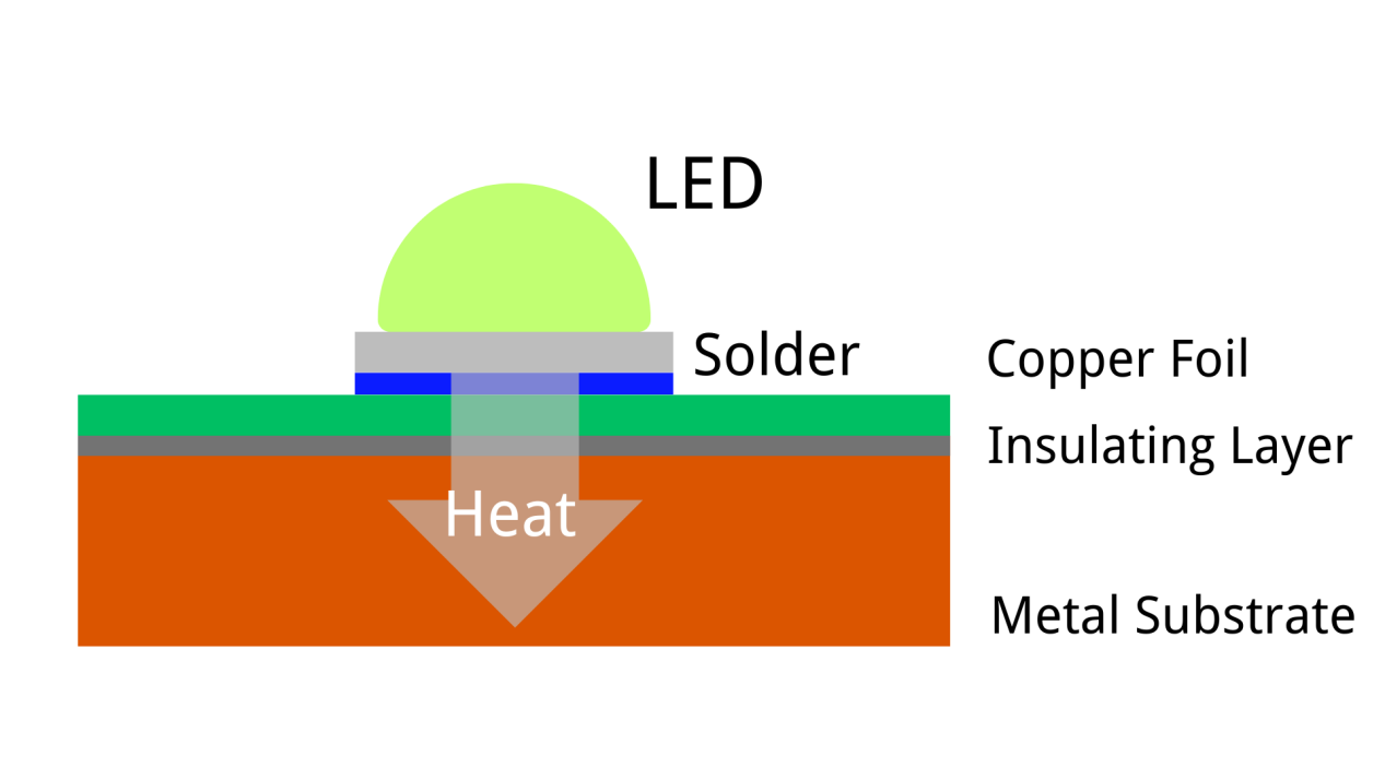
Additionally, there is a special category known as the thermoelectric separation copper substrate. Taking the application on LEDs as an example, the thermoelectric separation copper substrate is directly connected to the circuit leads of the LED beads, without going through the insulating thermal material. This allows the copper substrate to conduct heat efficiently, protecting the lifespan of the LEDs. Whereas the ordinary copper substrate uses insulating thermal material, as mentioned above, its thermal conductivity depends on the thermal coefficient of the material. However, the material's thermal conductivity generally does not surpass that of copper itself. Therefore, the thermoelectric separation copper substrate is more suitable for high-power LEDs, such as car lights, while the ordinary copper substrate is suited for low-power LEDs.
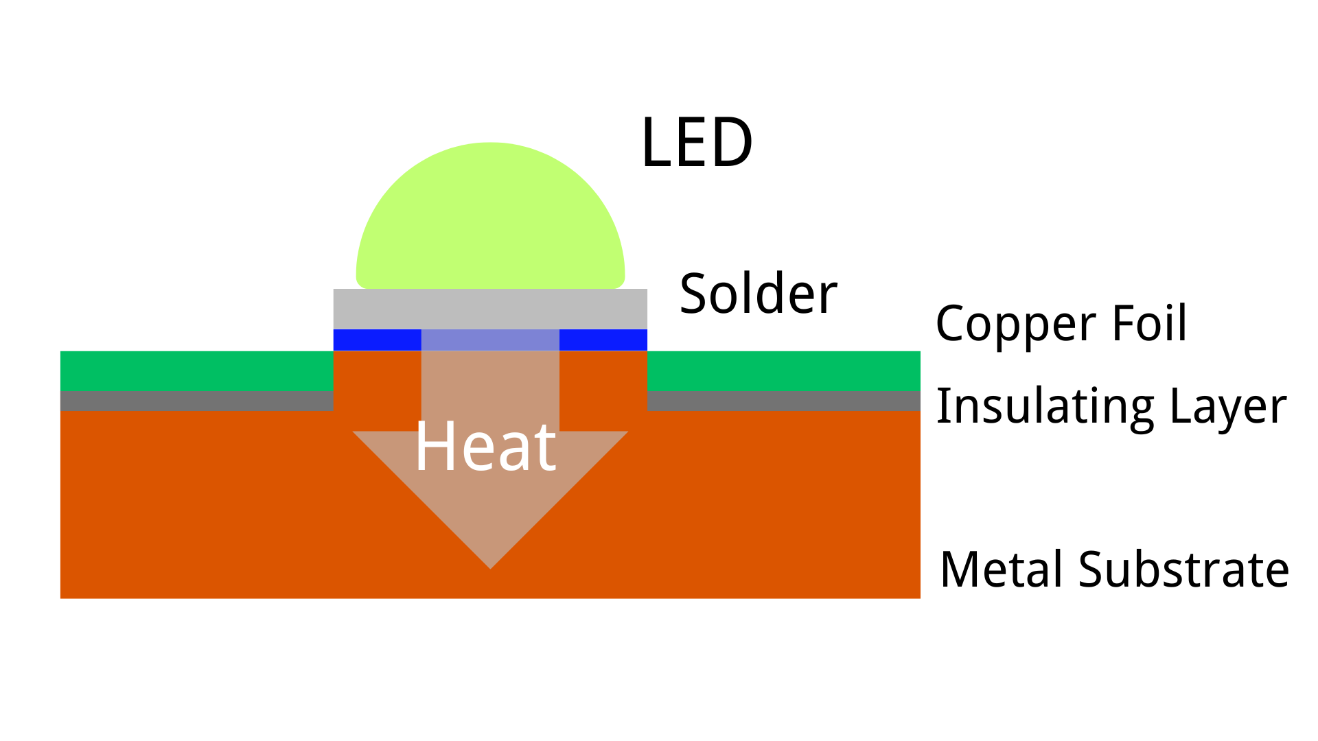
Thermoelectric Separation Copper Core PCBs
Iron Core Printed Circuit Board
The iron base material used for PCBs comes from special steel, silicon steel, etc., replacing FR4 or CEM1 substrates. This configuration allows heat to dissipate from critical circuit board components to less critical areas, such as a metal core or metal heatsink backplane. Most iron substrates on the market are single-sided aluminum substrates (green oil iron substrates), double-sided iron substrates, with thicknesses generally between 1mm-6mm. Iron substrates have a circuit layer equivalent to the copper-clad board of ordinary PCBs, with line copper foil thicknesses ranging from 1oz to 8oz. Iron substrates are mainly used for high-end motors, high-end product equipment, and metal heat-dissipating substrates for motors, currently widely applied in the market.
The hardness of the iron substrate compared to other metal substrates poses much greater manufacturing process and difficulty, and it is challenging for general manufacturers to master the technology. The main technical difficulties are:
1)Iron materials are extremely prone to oxidation and rust during processing, leading to poor adhesion with the insulating thermal layer and causing delamination;
2)Insufficient surface hardness, which easily leads to scratches during production and use by customers, becoming a bottleneck for product quality, cost, and processability;
3) High cost, to resolve adhesion as well as processability and applicability issues, requires investment in higher equipment and scrap costs. Thus, the market application scope is limited by cost, and there is also the issue of inadequate substrate thermal conductivity, unable to effectively meet the high heat dissipation needs of mechatronic equipment.
Therefore, communicating with the iron substrate manufacturer is essential to clarify their manufacturing process level and to confirm quality through prototyping.
Still need help? Contact Us: support@nextpcb.com
Need a PCB or PCBA quote? Quote now
Still, need help? Contact Us: support@nextpcb.com
Need a PCB or PCBA quote? Quote now
|
Dimensions: (mm) |
|
|
Quantity: (pcs) |
|
|
Layers: |
Thickness: |
|
|
|


