Support Team
Feedback:
support@nextpcb.com1. Frequency measurement
The frequency measurement is generally performed by a scanning spectrum analyzer, which scans the amplitude of each frequency signal and stores it under a certain resolution bandwidth (RBW), thereby displaying the information of the amplitude as a function of the entire frequency band. The RBW is an important consideration for scanning spectrum analyzers to provide excellent dynamic range and high accuracy of the static spectral components of the signal. However, the main disadvantage of a scanning spectrum analyzer is that it tests the amplitude of a frequency point of the signal only at one point in time.
This is a disadvantage because the RF signals of new wireless applications currently have complex time domain characteristics. The latest RF signals, especially the open industrial, scientific and medical (ISM) bands, often use spread-spectrum communication technologies such as Bluetooth and WiFi, and those signals are intermittent or bursty. The wireless signal of such a short duration is more noticeable in the frequency domain than the conventional wireless signal. Therefore, given the traditional scanning spectrum analyzer's ability to analyze and work with digital modulation, it is too difficult to use this instrument to test today's wireless signals. Even vector signal analyzers (VSAs) for specific digital modulation applications have limitations in analyzing specific signals that are frequency modulated over a period of time.
Today's spectrum detection often involves detecting basic events at non-fixed times and uncorrelated noise. Simply put, it includes instantaneous, predictable and unpredictable frequency shifts, complex modulation maps, and now a variety of RF and wireless communication standards and applications. Common examples are RFID and spread spectrum communication, where communication takes place very short or is a burst of signal. Although common scanning spectrum analyzers and vector analyzers have options for measuring these wireless communication methods, in this section we aim to use real-time spectrum analyzers (RTSA) for measurements. We discuss RTSA because today's infinite applications have tended to transient signals. SI engineers now need to trigger and capture signals that are of interest to them in both the time and frequency domains.
SI engineers often need to capture a continuous stream of signals, including instantaneous and frequency drift, and they need to get the frequency, amplitude, and modulation of the signal. In addition, all of this work often takes a long time to complete. For example, an SI engineer would have to wait for a long time to detect a transient event in a modern RF system using a scanning spectrum analyzer. Even then he will be limited, or he may have missed a measure of an emergency.
The idea of ??testing new RF applications is the change in the time domain of these wireless signals. This feature, combined with the factors discussed in the past, urgently requires a new test solution. As a result, SI engineers and designers are increasingly using real-time spectrum analyzers. Although RTSA is not new, it is similar to the VSA concept. RTSA is critical to the application of SI engineering. Therefore, today's SI engineers need to consider traditional frequency domain information and RTSA. In addition, although the current trend is that SI engineers have begun to recognize the importance of RTSA for potential time-domain and frequency-domain RF signal characteristics, this chapter discusses the reasons for focusing on RTSA.
2. Scanning spectrum analyzer
Traditionally designed scanning, superheterodyne spectrum analyzers have enabled engineers to measure the frequency domain for the first time decades. The former Scanning Spectrum Analyzer (SA) used pure analog devices early and quickly achieved success. The current new generation of scanning spectrum analyzers uses a high-performance digital infrastructure, including ADCs, digital signal processors (DSPs), and microcontrollers. However, the basis of the scanning principle is the same, and the instrument maintains its position as the underlying RF signal measurement tool. The outstanding advantage of the new generation SA is its excellent dynamic range, so it can capture and detect a wide range of RF signals.
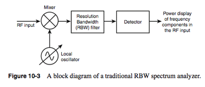
Power-frequency measurements can be achieved by downconverting the desired frequency of the signal and scanning through the RBW filter over the bandwidth. The RBW filter is followed by a detector for calculating the amplitude value of each frequency point in the passband, as shown in Figure 3.

Figure10-3 shows a test of the balance between frequency resolution and time. The local oscillator provides a "scan" frequency to the mixer, and each scan provides a different frequency and its corresponding value at the mixer output. The resolution filter is set to a user selectable frequency range, which is the resolution bandwidth (RBW). The narrower the filter bandwidth, the higher the resolution of the measuring instrument and the better the elimination of instrument noise. The RBW filter is followed by a detector to measure the frequency power of each frequency value instantaneously. Because this method can provide a higher dynamic range, its main advantage is that it can calculate the amplitude value of a frequency point at a certain point in time. If the RBW filter is designed to be too narrow, it takes a long time to complete a scan of the RF input, so that some changes in the input RF signal are not detected. Scanning in a frequency domain or in several passbands takes a considerable amount of time. The premise of this test technique is that the signal does not change significantly during the test period during which multiple scans are performed. Therefore, a relatively stable A constant input signal is required. If the signal changes frequently, you may not get the result.
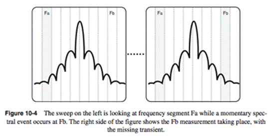
For example, the diagram on the left of Figure 10-4 shows the results of an RBW logic analyzer test. The frequency begins with Fa, and at a moment the frequency becomes Fb. When the scan reaches Fb, the signal has disappeared and is not detected, so the scan of the RBW spectrum analyzer cannot provide a trigger at Fb, thus failing to store a full signal condition for a period of time. This is a classic example of a balance between frequency resolution and test time and is the Achilles' heel of the RBW spectrum analyzer.

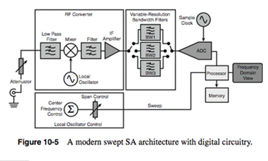
However, the latest scanning spectrum analyzers are much faster than traditional analog-based devices, and Figure 10-5 shows the architecture of a modern, excellent scanning spectrum analyzer. Traditional analog RBW filters have been digitally enhanced to facilitate fast and accurate narrowband filtering. However, the filters, mixers, and amplifiers before the ADC are all analog, especially considering the nonlinearities and noise in the ADC. Therefore, analog spectrum analyzers have a place to avoid the above problems.

Still, need help? Contact Us: support@nextpcb.com
Need a PCB or PCBA quote? Quote now