
 Surface


Lolly Zheng- Sales Account Manager at NextPCB.com

 NextPCB Capabilities
Printed Circuit Boards
NextPCB Capabilities
Printed Circuit Boards
 PCB Assembly
 Layer Buildup
 SMD-Stencils
 PCB Design-Aid & Layout
 Mechanics
 Quality
 Drills & Throughplating
 Factory & Certificate
 PCB Assembly Factory Show
Certificate
PCB Assembly Factory Show
Certificate
Support Team
Feedback:
support@nextpcb.com


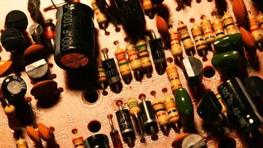
A Resistor is an electronic component fundamentally designed to introduce electrical resistance (R) into a circuit, thereby impeding the flow of electric current (I). As the most frequently utilized passive component, the resistor serves to quantify the opposition a material presents to current flow. This opposition is measured in Ohms (Ω) and arises from the physical conversion of electrical energy into thermal energy as charge carriers collide with the component's atomic structure.
Table of Content
Like current and voltage, resistance is the basic parameter of a circuit. Resistors are the most used components in circuits.
The resistor is arguably the most fundamental passive component in electrical engineering, yet its role has become increasingly critical in the context of high-speed and high-density electronic systems. Electrical resistance (R) quantifies the opposition a material presents to the flow of electric current (I).
As the name implies, a resistor is a component that hinders the flow of electric current and is the "dead rival" to electric current. This opposition arises at the atomic level: When a voltage is applied to a conductor, the charge flows through the conductor, and charge collision occurs during the flow, causing energy loss and limiting the current. Like mechanical friction that opposes movement, resistors oppose the movement of electric charge (current).
In physics, resistance is used to express the size of the conductor's obstructive effect on current. The greater the resistance of the conductor, the greater the resistance of the conductor to the current. Different conductors usually have different resistances, and resistance is a characteristic of the conductor itself.
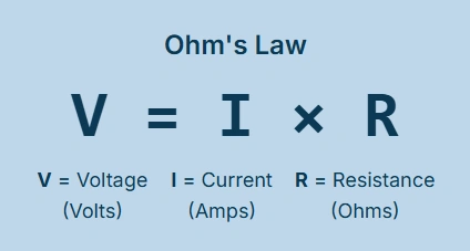
The relationship between current, voltage, and resistance is formalized by Ohm’s Law, which serves as the theoretical bedrock for circuit analysis. Voltage (V) is the electric potential difference (measured in Volts), and current (I) is the rate of charge flow (measured in Amperes). Resistance (R), measured in Ohms (Ω), is defined by the ratio of voltage to current. The cornerstone formula is expressed as V = IR. This simple algebraic relationship allows engineers to precisely determine unknown circuit characteristics—such as the required current limit or voltage drop—provided any two variables are known, forming the basis for designing everything from simple LED circuits to complex power converters.
Macroscopic resistance in a material is fundamentally governed by two factors: the material’s intrinsic resistivity (ρ) and its physical geometry.
The current in the circuit is similar to the water flow in the pipe. If the pipe is long enough, the water flow will become slow enough because of resistance. The same is true for resistors: if we increase the length of the conductor, the number of charge collisions will increase, and the movement of the charge will be further reduced.
The resistance of a conductor is generally related to temperature, material, length, and cross-sectional area. For example, under the same conditions, the longer the conductor, the greater the resistance; the larger the cross-sectional area, the smaller the resistance. The formula R = ρ(L / A) shows that resistance is proportional to the length (L) of the resistive path and inversely proportional to the cross-sectional area (A). Component manufacturers manipulate these geometric factors and material composition to achieve specific resistance values.
Resistive components are energy-consuming components that hinder current. The resistor’s practical function centers on power dissipation, known as Joule heating. The main physical characteristic of a resistor is to transform electrical energy into thermal energy. It can also be said that it is an energy-consuming element, and heat energy is generated when the current passes through it. The power (P) converted into heat within the resistor is defined by P = I2R or equivalently P = V2/R.
In modern systems, the inherent properties of resistance are viewed not just as component functionality but also as significant challenges to system-level performance. Since P = I2R means any resistance causes energy loss and a corresponding voltage drop (Vdrop = IR), this phenomenon has direct implications for Power Integrity (PI) in advanced printed circuit boards (PCBs). In high-current or low-voltage digital applications, even the minute resistance of power planes or traces, which are typically designed to be near-zero, results in localized voltage drops. This voltage variation across the power delivery network can destabilize the low operating voltages required by modern integrated circuits (ICs). Therefore, the resistor's fundamental property of opposing current flow is the ultimate antagonist to stable power delivery, requiring sophisticated design optimization and current sensing solutions.
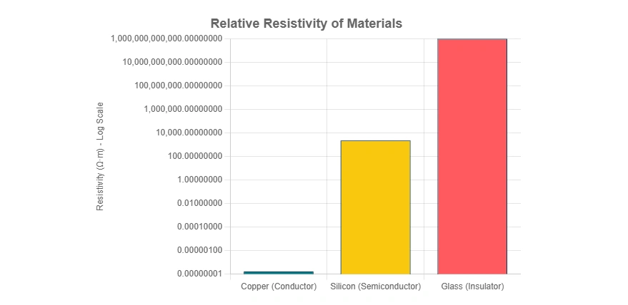
The material properties define a spectrum of resistance, which dictates whether a substance functions as a conductor or an insulator.
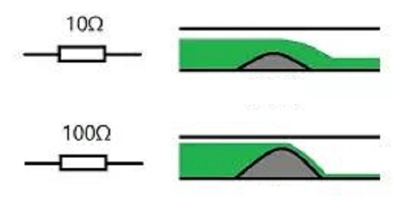
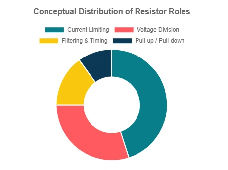
Resistance is not necessarily a bad thing. The main function of resistors is to limit current, reduce voltage (serial voltage division, parallel shunting), and convert electrical energy into heat. Like the friction that helps us walk and drive, resistors provide us with various conveniences.
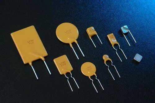
From the structure, resistors can be broadly classified into fixed resistors (where the resistance value is set during manufacturing) and variable resistors (where the value can be changed). Variable resistors include adjustable potentiometers and sliding rheostats. Physical quantity resistance sensors, such as thermal sensors, photosensitive sensors, pressure-sensitive sensors, and magnetic sensors, also fall into this category. The accuracy of fixed resistance is defined by its resistance and tolerance. Tolerance refers to changes caused by changes in temperature and light.
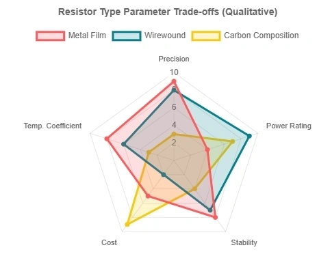
The construction technology employed directly determines a resistor's performance characteristics, including precision, thermal stability, and maximum operating frequency. Resistors are manufactured using various materials, including carbon, carbon film, metal film, thick film, foil, and wire-wound resistors. Carbon resistors are relatively old structures. The accuracy is low, and it is usually used where high-energy pulses are generated.
While the majority of resistors are mass-produced film components, specialized technologies remain essential for niche, high-performance applications. Wirewound resistors are constructed by winding resistive wire around a non-conductive core.
Wire wound resistors are the oldest structure; the resistance is accurate and is usually used in high-power applications. The small resistance is still very reliable. They are typically used when exceptional power handling (often exceeding 5 W) or extreme stability and a low Temperature Coefficient of Resistance (TCR) are required. However, the coiled nature of their construction introduces unavoidable parasitic inductance, which restricts their use primarily to DC or low-frequency AC applications.
Nowadays, metal and metal oxide resistors are used more frequently. The resistance value and tolerance are relatively stable, and the temperature coefficient is relatively good. For the highest precision demands, Bulk Metal Foil (BMF) resistors utilizes thin sheets of metal foil etched to achieve resistance. These components are used when TCR requirements are near 0.1 ppm/°C and tolerances are sub-0.01%, performance levels that far exceed the tightest mass-produced standards like the E192 series.
The vast majority of components used in contemporary electronics are Surface Mount Device (SMD) chip resistors, which are overwhelmingly based on film deposition technology. These are bifurcated into two dominant categories: thick film and thin film.
Thick film resistors are manufactured using a straightforward, cost-effective process involving the printing and firing of a special paste, which is a mixture of glass and metal oxides, onto an insulating ceramic substrate. This thick deposition provides a component with inherent robustness and superior power handling capabilities.
Thick film is generally preferred in applications where high precision and extreme stability are not critical requirements due to its significantly lower cost. These components typically feature tolerances between 1% and 5% and a TCR ranging from 50 to 200 ppm/°C. While offering high power handling capability, a wider range of resistance values, and superior ability to withstand high surge conditions, they exhibit lower long-term stability, with resistance changes (ΔR/R) typically ranging from ±1% to ±3% after 1,000 hours of load life testing at 70 °C (P70). Given their low cost and robustness, thick film chips dominate the market and can be found in almost any electrical device; an average personal computer, for example, may contain well over 1,000 thick film chip resistors.
Thin film resistors are produced through a more precise, capital-intensive process involving the vacuum deposition of a metallic film onto the substrate. This manufacturing technique yields significantly better performance characteristics.
Thin film components offer superior accuracy, a better temperature coefficient, and higher stability, competing directly with specialized components like wirewound technology. Stability is markedly higher, with resistance change limited to ±0.15% to ±0.5% after 1,000 hours of P70 testing. They also feature lower parasitic inductance and capacitance, making them generally favorable for high-frequency applications. Consequently, thin film resistors are specified for high-precision controls, measuring or monitoring equipment, and medical or audio applications.
The selection between these two film technologies involves balancing performance and cost:
| Characteristic | Thick Film | Thin Film |
|---|---|---|
| Tolerance (Typical) | 1% to 5% | 0.1% to 1% |
| TCR (Typical) | 50 to 200 ppm/°C | Better/Lower |
| Cost | Lowest | Medium |
| Power Handling | Higher, wider range | Medium |
| Stability at P70 (1000h) | ±1 to ±3% | ±0.15 to ±0.5% |
| Moisture Resistance | High (glass-like) | Lower |
It is important to note that the superior high-frequency performance generally attributed to thin film components requires careful consideration of manufacturing specifics. While thin film inherently offers lower parasitic inductance and capacitance, this advantage can be negated if the resistor is manufactured using a cylindrical shape that is spiral cut to trim the resistance value. The spiral cut geometry introduces inductance, which compromises performance in high-frequency signal paths. Therefore, signal integrity engineers must specify planar, non-spiraled designs for applications operating in the gigahertz range, ensuring the components remain purely resistive across the required operational bandwidth.
Component selection in modern electronics relies on standardized definitions for value, size, and critical operating limits.
> Recommend reading: Common Components on a PCBA and What Matters in Assembly
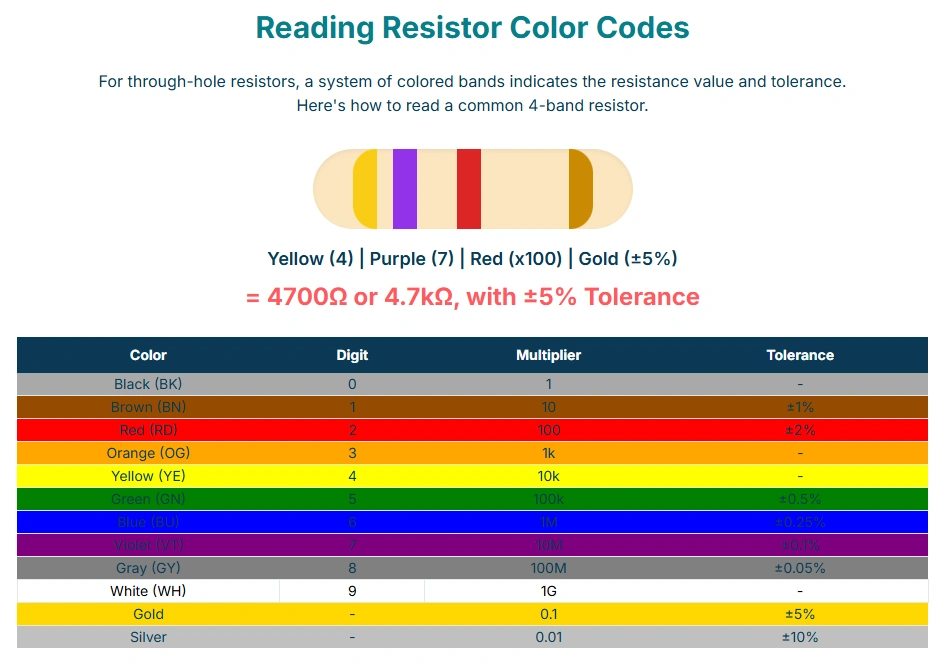
The resistance value is abbreviated as resistance value, and its basic unit is ohm, abbreviated as ohm (Ω). Commonly used units are kiloohms (kΩ) and megaohms (MΩ). The conversion relationship between them is 1 MΩ = 1000 kΩ, 1 kΩ = 1000 Ω. There are three ways to indicate the resistance value on the resistor: the direct labeling method, the color labeling method (color coding), and the digital labeling method. In electronic manufacturing, either 4-ring or 5-ring resistors can be used. In circuits such as frequency selection and bias circuit, resistors with small errors should be selected as much as possible. If necessary, an ohmmeter can be used to check the selection.
> Recommend reading: How to Achieve 50 Ohm Impedance Requirements for PCB Routing without extra charges
Resistor values are not manufactured arbitrarily. They adhere to the E-series standard, which dictates a geometric sequence of values within each decade magnitude (e.g., 1 Ω to 10 Ω, 10 Ω to 100 Ω). This structure ensures that a component manufactured to a specific tolerance level covers the entire ohmic range without gaps.
The E-series is categorized by the number of preferred values per decade, which is directly linked to the standard tolerance: E3, E6, E12, E24 are subsets of E24 and are typically rounded to two significant figures. E48, E96, and E192 are subsets of E192 and are rounded to three significant figures.
| E-Series | Number of Values per Decade | Maximum Error (Tolerance) | Significant Figures |
|---|---|---|---|
| E12 | 12 | 10% | 2 |
| E24 | 24 | 5% | 2 |
| E96 | 96 | 1% | 3 |
| E192 | 192 | 0.5% (and lower) | 3 |
The precision of the resistance is generally 1% and 5%,and the precision can be as low as 0.1%. The price of 0.1% is about ten times that of 1%,and the price of 1% is about 1.3 times that of 5%. The high density of E192 values (offering 192 distinct values per decade, necessary for tolerances as low as 0.1% ) allows designers to define scaling factors with extreme precision.
Rated power is another main parameter of resistors. Commonly used resistors have 1/8 W、1/4 W、1/2 W、1 W、2 W、5 W, etc. In operation, a resistor with a rated power equal to or greater than the circuit request should be selected. What is not marked in the circuit diagram means that the power consumption of the resistor is very small, so there is no need to think about it.
The Temperature Coefficient of Resistance (TCR) is a crucial metric, measuring the stability of the resistance value against changes in temperature, expressed in ppm/°C. This is mainly determined by the material of the resistor. Generally, the package of thick film chip resistors above 0603 can achieve 100 ppm/°C,which means that when the ambient temperature of the resistor changes by 25 degrees Celsius,the resistance value may change by 0.25%. In more demanding precision instruments, metal film resistors are used. It is easy for them to achieve a temperature drift of 10 to 20 ppm, and of course, it is more expensive. In short, the temperature coefficient is definitely a very important parameter in the precision applications of instruments. Inaccurate resistance can be adjusted during calibration, and the change of resistance with external temperature cannot be controlled.
SMD chip resistors are defined by standardized package codes, which often reference both imperial (inches) and metric (millimeters) dimensions. The physical size of the package directly dictates the component’s maximum rated power handling capacity and its mechanical robustness.
Standard imperial codes such as 0805 denote dimensions of 0.08 inches by 0.05 inches, translating to 2.0 mm by 1.3 mm. As technology drives miniaturization, the power handling capacity decreases dramatically. Extremely small components, such as the 0402 size, are typically rated for as little as 1/16 W (0.063 W), while larger chips like the 2512 size can handle 1 W to 2 W.
| Code (Inches) | Dimensions (mm) | Typical Rated Power @ 70 °C (W) |
|---|---|---|
| 0402 | 1.0 x 0.5 | 1/16 (0.063) to 0.100 W |
| 0603 | 1.6 x 0.8 | 1/10 (0.10) to 0.125 W |
| 0805 | 2.0 x 1.3 | 1/8 (0.125) to 0.200 W |
| 1206 | 3.0 x 1.5 | 1/4 (0.25) to 0.400 W |
| 2512 | 6.4 x 3.2 | 1 W to 2 W |
The voltage that can be applied at both ends of the resistor is determined by the rated power. It is necessary to ensure that the power does not exceed the rated power, and to consider the maximum withstand voltage of the resistor. For example, the withstand voltage for some packages includes: 0603 = 50 V, 0805 = 100 V, 1206 to 2512 = 200 V, and 1/4 W through-hole = 250 V. Moreover, in a long-term application, the voltage on the resistor should be more than 20% less than the rated withstand voltage value, otherwise, problems will easily occur over a long period of time.
A resistor’s Rated Dissipation (PRated) defines the maximum electrical power it can safely convert into heat when the ambient or specific reference temperature is maintained, typically 70 °C. To maximize power density, some components offer specialized "Power" mode ratings, increasing capacity (e.g., an 0805 standard 0.125 W vs. a power 0.200 W version ). This enhanced rating is achieved by engineering the component to tolerate a higher permissible film temperature (ϑFmax),potentially up to 155 °C.
The principle of power derating requires that the power applied to the resistor must be linearly reduced (derated) when the component’s operating temperature rises above a specified threshold, often 70 °C or 125 °C. This control mechanism is essential to prevent thermal runaway and permanent damage to the resistive film.
In modern engineering, the derating determination has shifted from relying solely on ambient temperature to using the Terminal Part Temperature—the temperature measured where the component connects to the PCB pad. This provides a much more accurate and localized assessment of thermal stress within a dense circuit environment. The power derating curve plots the maximum allowed Rated Power Ratio (%) against the Terminal Part Temperature.
This precise thermal analysis enables advanced engineering practices, particularly component downsizing.
For instance, if an engineer is testing a circuit where the applied power is 0.1 W, but the terminal temperature is 140 °C,the derating curve is essential. At 140 °C,the curve may mandate a 50% Rated Power Ratio (0.5). The necessary rated power (PNeeded) for the resistor must therefore be Calculated as: 0.1 W ÷ 0.5 = 0.2 W. If the designer chooses an 0805 size resistor rated at 0.25 W, it is deemed safe since PRated (0.25 W) is greater than PNeeded (0.2 W). Following this thermal management protocol allows for the safe use of smaller components, whereas a conservative, traditional design rule (e.g., staying below 30% of rated power regardless of temperature) might require stepping up to a larger 1210 package.
Current sensing resistors, often called shunts, are critical for power management systems in battery control, motor drives, and power supplies. Their purpose is to generate a minute, measurable voltage drop (V=IR) across an extremely low resistance element (typically in the milliohm (mΩ) range, down to 0.00055Ω). The measured voltage drop is then used to accurately monitor current flow. These components must feature exceptionally high stability, low TCR, and often non-inductive designs to operate accurately in high-frequency switching environments. They are available in high-power formats, sometimes handling 16 W up to 100 W continuously.
For ultra-low resistance values, traditional two-terminal measurement methods introduce unacceptable error because the resistance of the connecting leads and solder joints becomes comparable to the resistor value itself. To overcome this, precision current shunts utilize a 4-terminal (Kelvin) connection. Two outer terminals carry the high current, while two inner voltage taps measure the voltage drop directly across the resistive element. This methodology cancels out the parasitic resistance of the connection points, ensuring highly accurate measurement necessary for high-fidelity current feedback loops.
Fusible resistors are designed to serve a dual purpose: providing a specific resistance value while also acting as a reliable fuse. When an overload condition occurs, the fusible element fails open circuit, protecting subsequent, more expensive circuitry. These are typically thick film components with resistance ranges up to 1.8 KΩ. Additionally, power film resistors are often designed to be electrically isolated and flameproof, sometimes meeting demanding flammability ratings equivalent to UL94-V-0.
A resistance of 0 ohms is common in circuit design, and everyone is often confused: Since it is a resistance of 0 ohms, it is a wire, why should it be installed? (In fact, the resistance of a zero-ohm resistor is not "0Ω", but very small, almost 0.) A typical working resistor value, such as 10KΩ Resistance Value,performs standard functions like voltage division or pull-up duty, whereas 0Ω is reserved for specific circuit architecture strategies.
The zero-ohm resistor, frequently packaged in standard SMD sizes (e.g., 0603), has a nominal resistance of 0Ω. Crucially, while acting as a wire link, it possesses finite parasitic impedance (resistance and inductance), which is utilized strategically in complex circuit design.
A primary application is bridging digital and analog grounds in mixed-signal boards (single-point grounding). These ground planes must be kept separate to minimize digital noise coupling but must ultimately connect to a common earth potential. The 0-ohm resistor provides a controlled, single-point connection, acting as a very narrow current path that effectively limits loop current and suppresses noise better than a wide-area connection.
For EMC countermeasures, connecting a 0-ohm resistor across a split ground area prevents the signal return loop from taking a wide detour, which otherwise creates a large loop area, intensifying the influence of electric and magnetic fields and increasing susceptibility to interference. By providing a short return path, the 0-ohm resistor minimizes the loop area and significantly reduces noise and interference.
The 0-ohm resistance can be used in PCB design instead of wires and jumpers. For example, the use of zero-ohm resistors in PCB mass production can reduce costs and can also effectively reduce the risk of PCB design being copied, as it can confuse and prevent PCBs from being copied. Designers and manufacturers will place 0-Ω resistors where there is no resistance value or use different color codes for the resistors. They are also used to cross traces, where their parasitic inductance is smaller than that of a plated-through-hole via, and their use avoids disturbing the critical ground plane integrity required by a via.
Signal integrity (SI) is a measure of how accurately an electrical signal’s waveform is preserved between entering and exiting a circuit. High-speed digital signals are prone to degradation (noise, distortion, and timing shifts) caused by resistance in the materials, capacitance, and electromagnetic coupling between traces. Resistors are indispensable for mitigating these effects, primarily through impedance control.
High-speed circuit traces and communication cables act as transmission lines characterized by a specific characteristic impedance (Z0), typically ranging from 100 Ω to 150 Ω for differential twisted-pair cables, or 50 Ω for single-ended traces.
If a signal encounters an impedance mismatch—such as an open circuit or a load resistance unequal to Z0—a portion of the energy is reflected back up the line. This reflected energy can interfere with subsequent signals, potentially causing destructive interference and bit errors. To prevent this, termination resistors are placed, usually at the end of the bus. By matching the load resistance to the characteristic impedance of the transmission line, reflections are eliminated, ensuring maximum signal power reaches the receiver. For example, the RS-485 standard mandates the use of 120Ω parallel termination resistors to match the nominal impedance of the bus cable.
In digital logic and communications interfaces, resistors are used in pull-up or pull-down configurations to ensure signal lines do not float in an uncertain, high-impedance state, which severely degrades noise tolerance.
Pull-up resistors clamp the uncertain input signal to the supply voltage (VCC),while pull-down resistors clamp it to ground. This is essential in open-drain or open-collector systems (such as I2C or CAN buses) where the driver goes passive (high impedance) to define the recessive logical state. The pull-up resistor defines this high logical level.
Selecting the appropriate resistor value is a balancing act. A lower resistance ("strong pull") provides faster signal rise/fall times, which is favorable for switching speed, but results in higher power consumption and greater current draw. A higher resistance ("weak pull") conserves power but slows switching speed.
While chip resistors are generally robust, failures do occur, predominantly resulting in an increase in resistance value or a complete open circuit (wire breakage).
Modern electronic systems often face harsh environments that compromise traditional resistor designs.
Sulfurization (Sulphur Contamination): A critical failure mode where silver, commonly used in internal resistor electrodes, reacts with environmental sulfur (found in industrial air or certain packaging materials) to form non-conductive silver sulfide. This reaction causes a catastrophic increase in resistance or an open circuit. To address this, especially in automotive and industrial sectors, mandatory adoption of anti-sulfur chip resistors—which incorporate non-silver or protected barrier metal electrodes—is required, often complemented by protective conformal coatings.
Migration and Electrolytic Corrosion: These are related failures occurring under conditions of high humidity and applied voltage. Migration involves the ionization of anode metal, which moves toward the cathode and regrows as tree-like dendrites, eventually leading to short circuits. Electrolytic Corrosion primarily affects thin film components under humid conditions and voltage, degrading the resistive element and increasing resistance.
| Failure Mode | Failure Effect | Primary Cause | Applicable Type |
|---|---|---|---|
| Sulfurization | Resistance increase/Open circuit | Environment containing sulfur | All (Internal electrode) |
| Migration | Resistance reduction/Short circuit | High humidity/Halogen attachment | All (Internal electrode) |
| Electrolytic Corrosion | Resistance increase/Open circuit | High humidity/Voltage | Thin film type |
| Resistive Element Burnout | Resistance increase/Open circuit | Electrical overload | All types |
A multimeter can be used to measure the resistance value and determine whether the resistance is good or bad. The actual resistance value can be measured by connecting the two test leads (regardless of positive and negative) to the pins at both ends of the resistor. In order to improve the measurement accuracy, the range should be selected according to the nominal value of the resistance being measured. If the measurement result is very different from the market value on the resistor, it means that the resistor has been damaged. (Analog multimeter needs to be calibrated to 0 before measurement, a digital multimeter is not used)
For validating resistance values, a standard two-terminal ohmmeter is sufficient for high-value components (kilohm range and above). However, measuring low-value current shunts requires Precision Measurement with Kelvin Probes (4-Wire Sensing). Just as with Kelvin-terminated components, this technique uses two leads to inject current and two separate leads to measure the voltage drop. This methodology eliminates the resistance contributed by the test leads and contact points, ensuring that the measured value accurately represents only the resistive element itself.
In addition, resistance is affected by many factors. Therefore, the following factors must be considered when measuring resistance:
The following are the common formulas used to calculate resistance, power, and energy in electrical circuits:
The resistor remains a pivotal component, moving far beyond a simple current limiter to become an essential element in high-performance power delivery and signal integrity management. Modern selection requires a multivariate analysis of operational requirements:
The trajectory of resistor technology is tightly coupled with advances in semiconductor miniaturization and data speed requirements. Future developments will focus heavily on:
Q: What happens if I use a resistor with a higher resistance than required?
A: Using a higher resistance will reduce the current more than intended. For example, in an LED circuit, this would make the LED dimmer or prevent it from lighting up at all. In a voltage divider, it would alter the output voltage. It's generally safer than using too low a resistance but will likely cause the circuit to malfunction.
Q: Why do resistors get hot?
A: Resistors dissipate electrical energy as heat, a phenomenon known as Joule heating. As electrons collide with the atoms of the resistive material, their kinetic energy is converted into thermal energy. According to a study on thermal management in electronics on Science Direct, this heat must be managed to ensure component reliability. The power dissipated as heat is calculated by P = I²R.
Q: Can resistors be connected in any direction?
A: Yes, most common resistors (like carbon film, metal film, etc.) are non-polarized components. This means they can be connected in a circuit in either direction without affecting their function. The current can flow through them from either lead. This simplifies assembly and design. Some specialized components that have resistance may be polarized, but standard resistors are not.
>> Recommend reading: Current Sense Resistor: Low Ohm Shunt Selection, PCB Layout and Kelvin Connection
Ready to implement your design or need specialized manufacturing? Access our services directly:
Need Technical Support?
Start Manufacturing:
Get an instant PCB or PCBA quote now

Still, need help? Contact Us: support@nextpcb.com
Need a PCB or PCBA quote? Quote now


enjrie
Nice articles, basic knowledge of components is important for engineers.