
 NextPCB Capabilities
Printed Circuit Boards
NextPCB Capabilities
Printed Circuit Boards
 PCB Assembly
 Layer Buildup
 SMD-Stencils
 PCB Design-Aid & Layout
 Mechanics
 Quality
 Drills & Throughplating
 Factory & Certificate
 PCB Assembly Factory Show
Certificate
PCB Assembly Factory Show
Certificate
Support Team
Feedback:
support@nextpcb.com


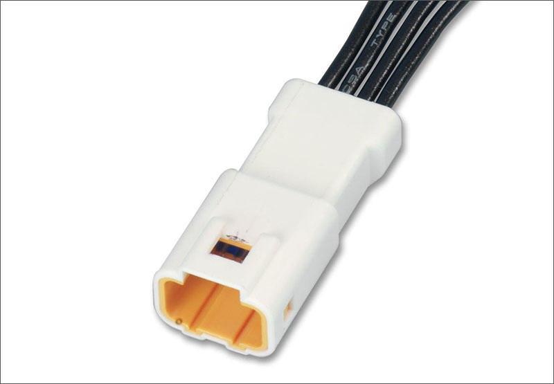
Printed Circuit Board connector, also known as PCB connector, is a fundamental part of any electronic device; they provide the connection between a circuit board and its components. From consumer appliances to automobile engineering and aerospace technology - these versatile elements can be found in an array of industries across the globe. Their reliable performance makes them integral assets for ensuring efficient functioning within our technological world!
PCB connectors are essential to ensure a solid, dependable connection between two or more circuits. Whether it's for transmitting power, data or signals from one device to another - these connectors guarantee an effective transfer of information in any environment. Available in numerous sizes and forms that can cater to all your needs, the possibilities for customization with PCB connectors are practically endless!
As you look for the ideal PCB connector, a crucial aspect to keep in mind is the pitch - or spacing between its pins and contacts. This interval may differ depending on both size and type of connector, so it's essential to consider this when factoring in your board design's overall dimensions. Other important factors to consider when selecting a PCB connector include the termination method, materials and coatings, and connector features such as locking mechanisms and keying.
Depending on the usage and conditions, PCB connectors can be securely attached by using either a through-hole or surface-mount technology (SMT) process. Through-hole mounting requires inserting the connector pins into drilled holes in the circuit board while SMT necessitates attaching them to its surface directly.
When selecting the best PCB connector for your application, there are a variety of options available. From custom-made connectors to common types like FPC/FFC and D-Subminiature, you will find one that meets precisely what you require. Here's a list of some of the most popular varieties:
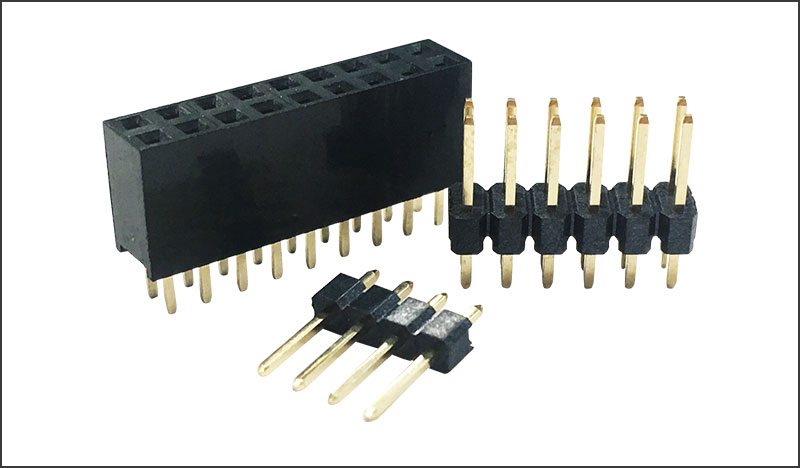
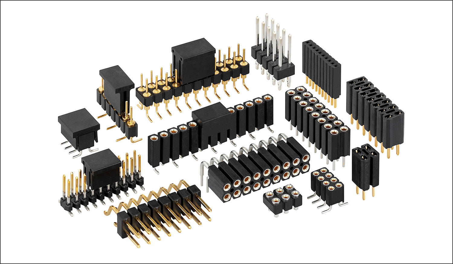
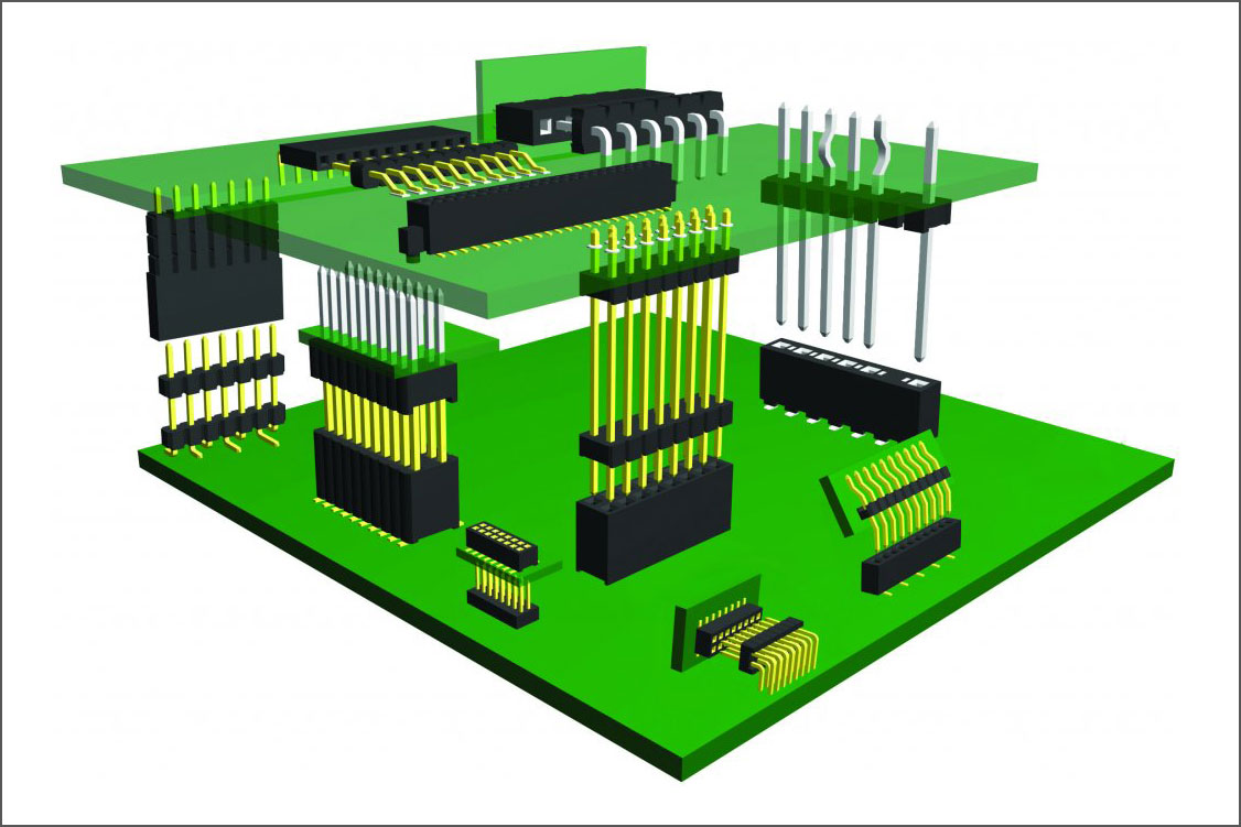
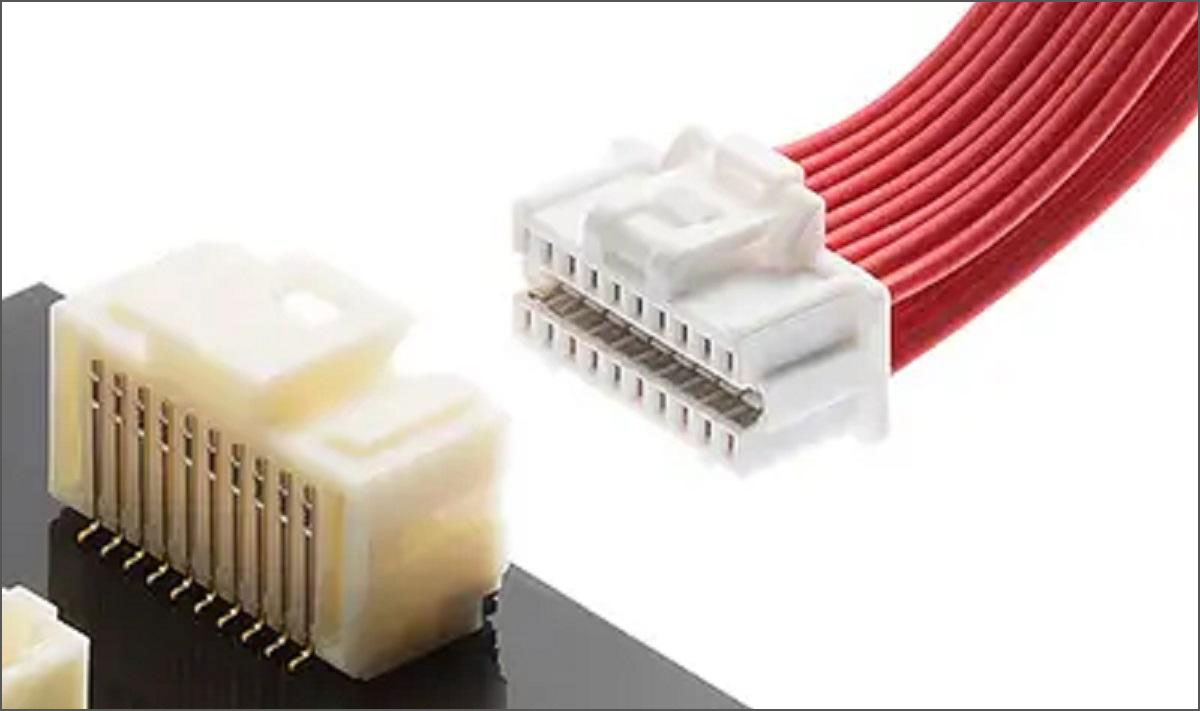
These male connectors feature rows of pins and are widely used for board-to-board and wire-to-board connections. They are available in various configurations, including straight, right-angle, and surface-mount, and have different pin spacings and numbers of pins to accommodate diverse applications.
These female counterparts to pin headers have rows of receptacles designed to mate with pin headers. They are used in applications like board-to-board and wire-to-board connections and are available in multiple configurations, including straight, right-angle, and surface mount.
Mezzanine Connectors: These connectors enable vertical or parallel connections between two PCBs at a short distance, providing high-density interconnects for applications like data processing, communication, and industrial equipment.
Stacking Connectors: These connectors allow for PCBs to be connected vertically in a stacked configuration. They are used in applications where space is limited, and multiple boards need to be connected without using additional cables.
Card Edge Connectors: These connectors are designed to connect a PCB to another by sliding the board's edge into the connector's slot. They are commonly used for connecting expansion cards, such as graphics cards and RAM modules, to motherboards.
Crimp-style Connectors: These connectors involve crimping a contact onto the wire, which is then inserted into a housing that mates with a PCB-mounted connector. They provide a secure and reliable connection in a variety of applications.
IDC (Insulation Displacement Connector) Connectors: These connectors pierce the insulation of a wire to establish an electrical connection without the need for stripping or soldering. They are commonly used for ribbon cables and offer a quick and reliable connection method.
Terminal Block Connectors: These connectors use a screw or spring mechanism to clamp the wire, providing a secure connection to the PCB. They are used in applications that require easy wire insertion and removal or where multiple wires need to be connected to a single point on the PCB.
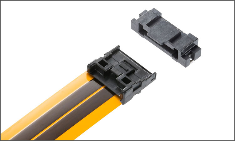
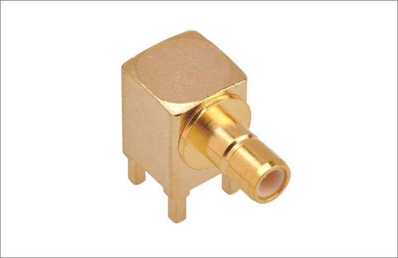
These connectors are designed to connect FFCs or FPCs to PCBs. They offer a compact, low-profile connection that is ideal for tight spaces and applications requiring flexibility or high-density connections, such as in laptops, mobile devices, and wearable electronics.
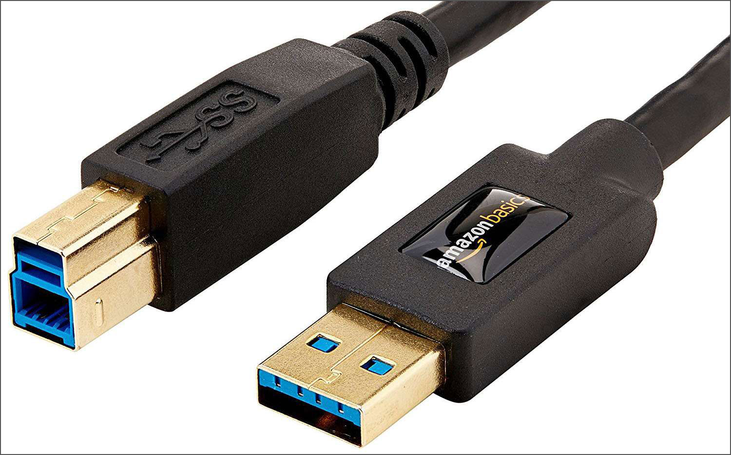
These connectors facilitate data transfer and power supply between electronic devices and peripherals. They are commonly found on PCBs for connecting USB devices like thumb drives, keyboards, and cameras. There are several types of USB connectors, including USB Type-A, Type-B, Type-C, and Micro-USB.
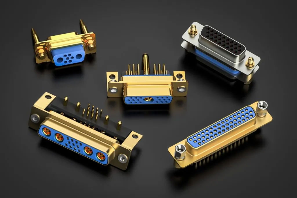
These connectors have a D-shaped metal shell and are widely used for data and video signal transmission. They are available in various pin configurations, such as 9-pin (DE-9), 15-pin (DA-15), and 25-pin (DB-25), and are commonly used for RS-232 serial connections, VGA video connections, and parallel printer ports.
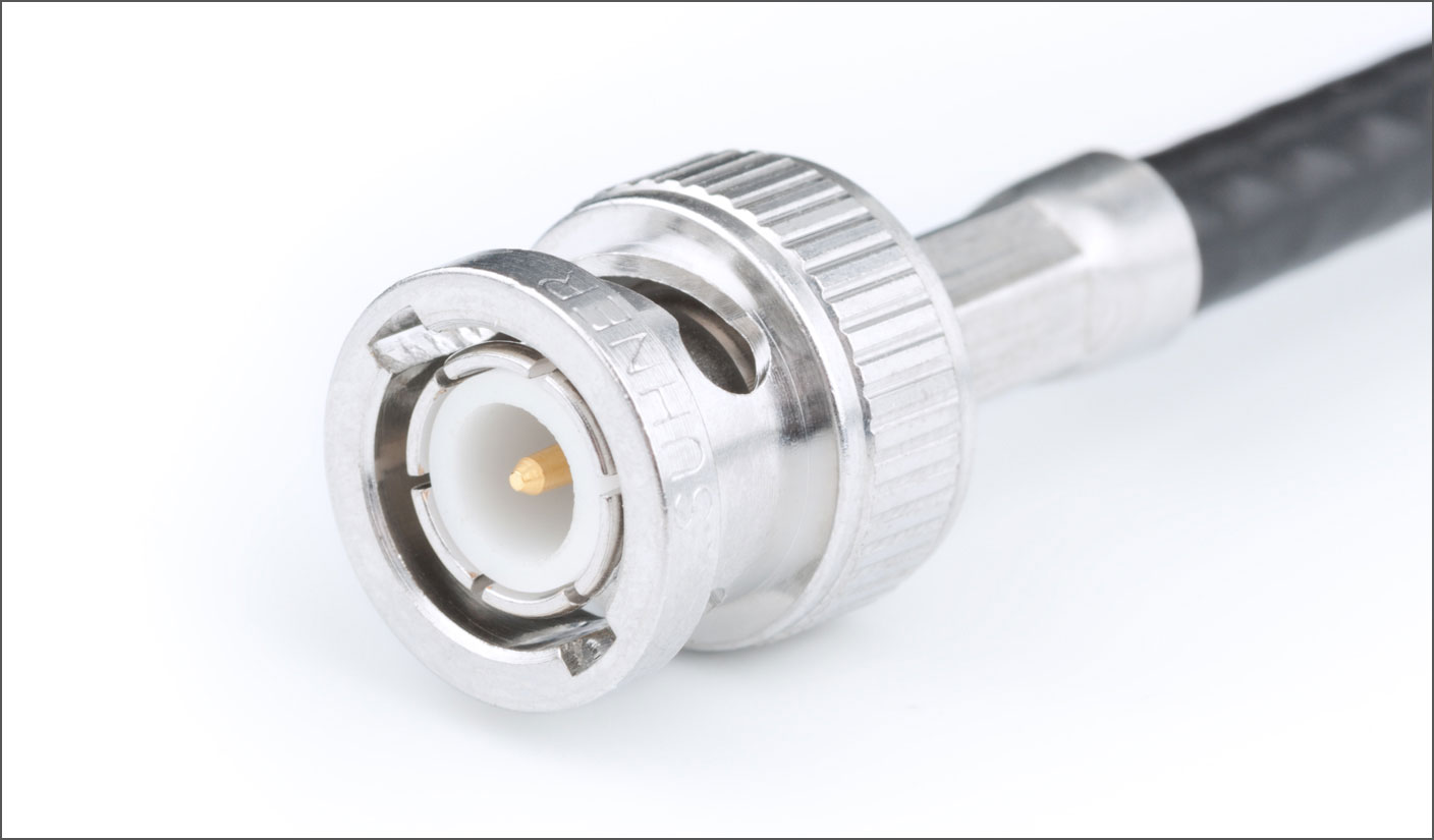
These connectors feature a bayonet locking mechanism and are primarily used for radio frequency (RF), video, and data connections. They provide a secure and reliable connection in applications like test equipment, broadcast, and telecommunications.
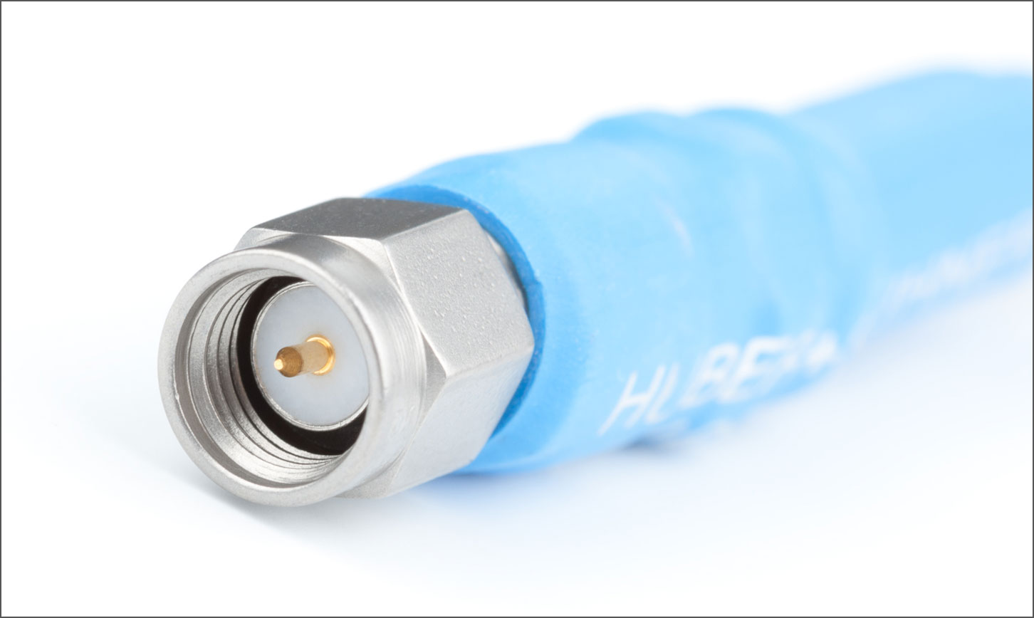
These coaxial connectors are designed for use in high-frequency applications, such as antennas, test equipment, and microwave systems. They offer reliable performance, low insertion loss, and excellent electrical characteristics, making them suitable for various RF and microwave applications.
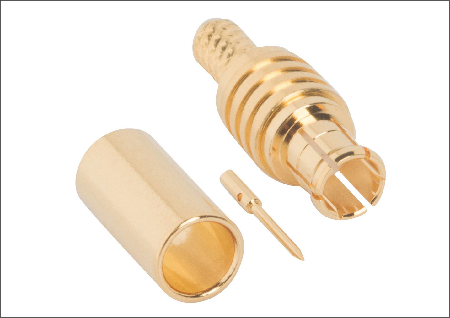
These small, snap-on coaxial connectors are used in high-frequency applications where space is limited. They offer similar electrical performance to the SMA connectors but in a more compact design, making them ideal for use in GPS receivers, antennas, and other small devices.
These connectors are even smaller than MCX connectors and are used in applications where space and weight constraints are critical. They are commonly found in wearable devices, mobile phones, and other compact wireless communication systems.
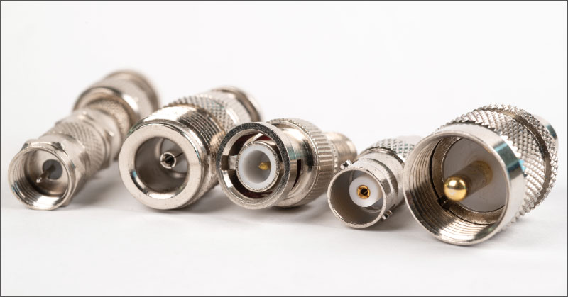
These connectors are designed specifically for transmitting radio frequency signals. They come in various types, such as SMA, BNC, and N connectors, and are used in applications like antennas, test equipment, and wireless communication systems.
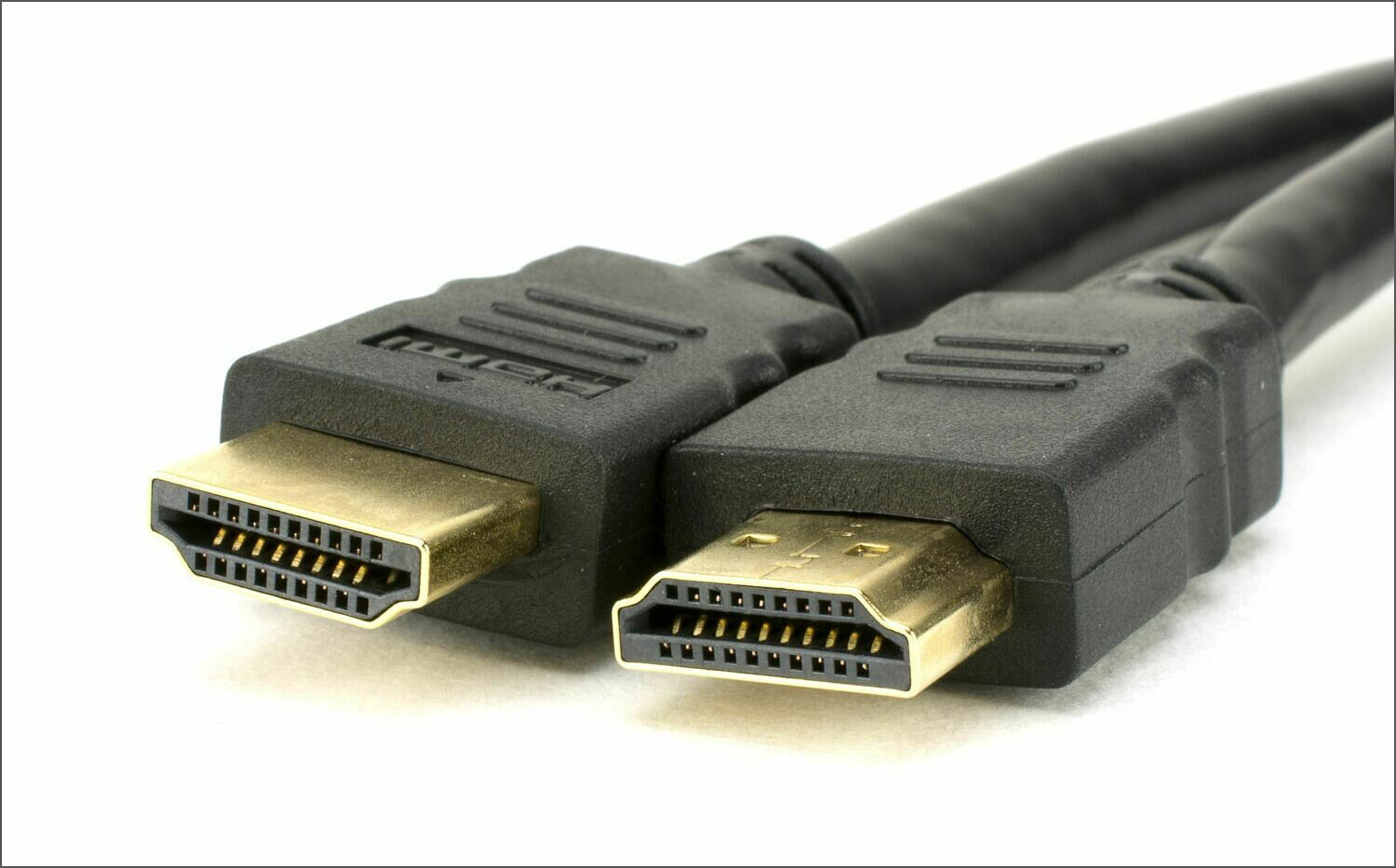
These connectors transmit high-definition audio and video signals between devices like TVs, monitors, and media players. They are commonly found on PCBs for connecting devices that require high-quality digital video and audio transmission.
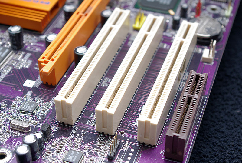
These connectors provide high-speed data connections between a motherboard and various expansion cards, such as graphics cards, network cards, and solid-state drives. They enable fast data transfer rates and are a standard feature on modern motherboards.
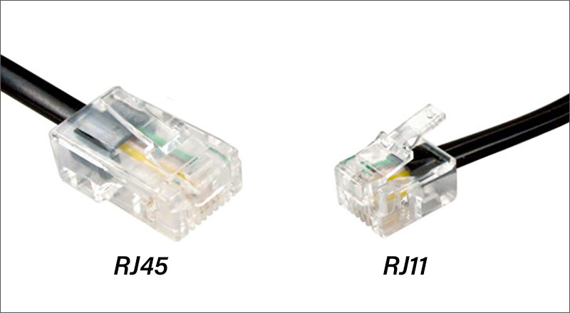
RJ11 (Phone line) Connectors: These connectors are used for connecting telephone lines to devices like phones, modems, and fax machines. They typically have 2 to 6 contacts and are the standard connector type for telephone systems.
RJ45 (Ethernet) Connectors: These connectors are used for networking applications, such as connecting Ethernet cables to devices like switches, routers, and computers. They have 8 contacts and are the standard connector type for Ethernet networks.
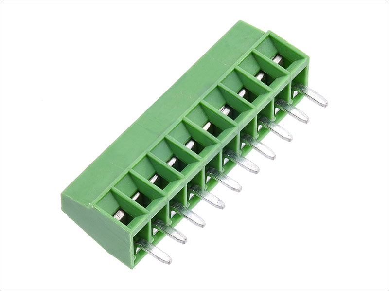
These connectors use screws to secure wires, providing a robust and reliable connection to the PCB. They are commonly used in power supply and control applications, such as industrial equipment and automation systems.
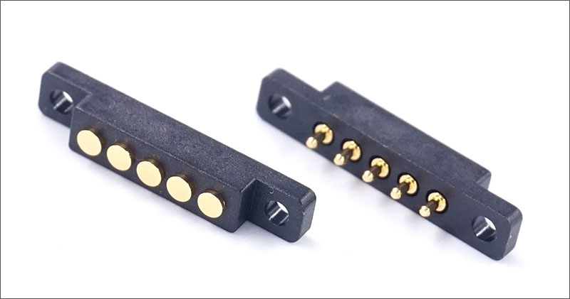
These connectors use spring-loaded pins to make temporary electrical connections. They are commonly used in test equipment, charging stations, and battery connections, where quick and reliable connections are required.
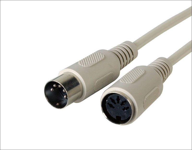
These connectors are standardized by the German national standards organization and come in various configurations for different applications, such as audio, video, and data transmission. Examples include the 5-pin DIN connector used for MIDI devices and the 7-pin DIN connector used for analog video signals.
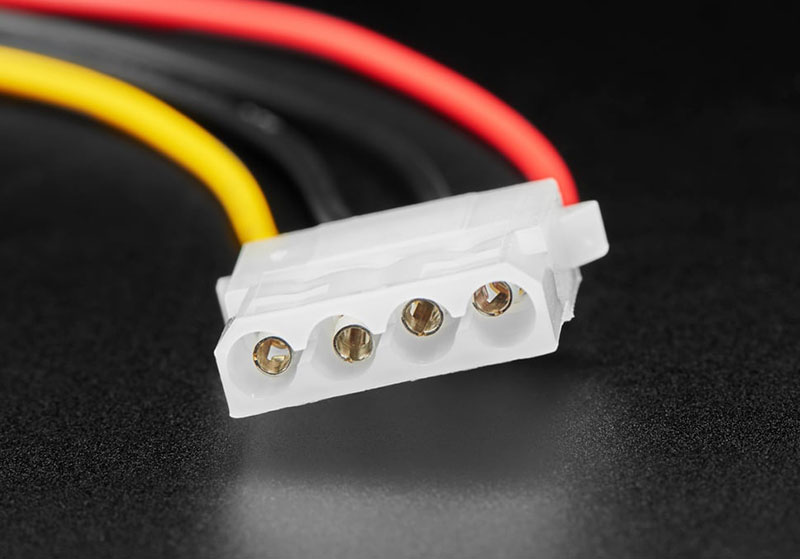
These connectors are a brand name for a wide range of connector types, including board-to-board, wire-to-board, and power connectors. They are used in various applications, such as automotive systems, consumer electronics, and computer peripherals.
These connectors are a brand name for a wide range of connector types, including crimp-style and insulation displacement connectors. They are used in various applications, such as consumer electronics, automotive systems, and industrial equipment.
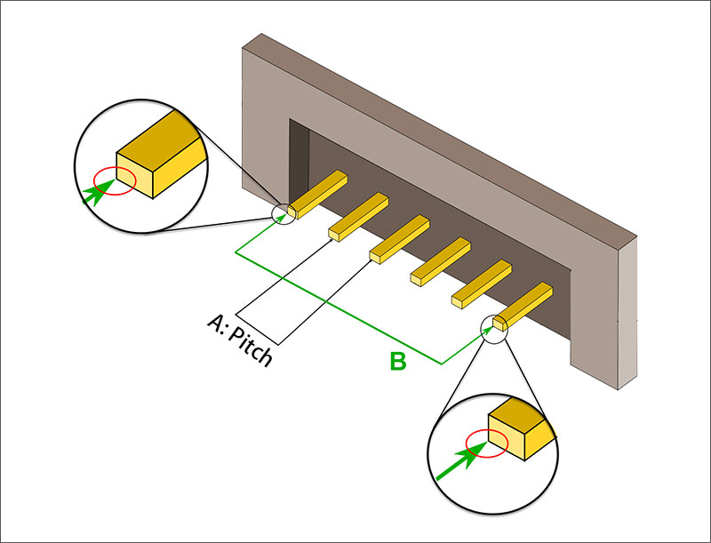
When selecting a PCB connector, the pitch and size are essential considerations. Pitch is the distance between contacts while size accounts for its total dimensions such as width, length, and height. These parameters can affect not only your circuit board's design. But also the electrical/mechanical efficiency of the system itself - so make sure to take them into account!
Connectors come with various pitches, ranging from something as small as 1mm to more than 5mm for larger connectors. A minuscule pitch can offer a higher pin count in one space but may be difficult and time-consuming to manufacture. On the other hand, a larger pitch will streamline production and mating yet limit the number of pins allowed within an assigned area.
The size of the connector depends on a variety of factors, including space available on the circuit board and its desired electrical and mechanical performance. While some connectors are designed to be small yet powerful, others may need to be bigger and stronger for use in tougher conditions.
In order to choose the right connector for your application, it is important to take into account its pitch and size. The chosen product should not only fit in the available space on the printed circuit board. But also be capable of providing reliable electrical as well as mechanical performance. Moreover, it must be compatible with other connectors or devices so that a safe connection is established between them.
When choosing a PCB connector, apart from the pitch and size of the device, there are several other essential elements to mull over. Here's a list of some key features you should keep in mind:
Proper installation and maintenance of PCB connectors are critical for ensuring reliable and long-lasting performance. Here are some best practices for installing and maintaining PCB connectors:
PCB connectors have a wide range of applications in various industries and products. Here are some common applications of PCB connectors:
In conclusion, PCB connectors play a vital role in ensuring the proper function and performance of various electronic systems. They provide a reliable and efficient way to connect internal and external components to the PCB, allowing for seamless communication and power transfer. There are various types of PCB connectors available, each with its unique features and applications. A suitable selection of connectors for each application is essential to guarantee optimal performance. Adhering to expert recommendations during the installation and maintenance of PCB connectors will ensure they remain reliable with long-term results. By utilizing best practices, designers and technicians alike can maximize the effectiveness of PCB connectors in their applications. Overall, PCB connectors are an essential component in the design and development of electronic systems, and their importance cannot be overstated.
Still, need help? Contact Us: support@nextpcb.com
Need a PCB or PCBA quote? Quote now


 Surface

