A Brief Introduction to SPDT Switch
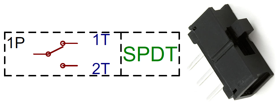
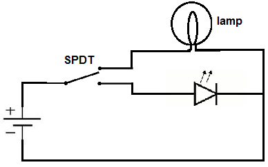
An SPDT switch (Single Pole Double Throw switch) is an electrical switch that has one input terminal and two output terminals. The designers specifically created this device to connect the input terminal to only one of the two output terminals at a time, and not to both simultaneously.
This article discusses the SPDT switch wiring in advance.
You can manually operate the switch's moving contact or lever to connect the input to either of the output terminals.
In its resting or "off" position, the switch does not connect the input to either of the output terminals.
By activating the switch, you can link an input to one of two different outputs and detach it from the other—allowing for a smooth transition between them.
The SPDT switch is an incredibly flexible tool for electrical engineers; it allows them to control the current or voltage in their circuits with tremendous precision. Many different types of electronics, such as amplifiers, power sources, and household appliances, widely utilize it from audio systems to industrial control networks and everything in between.
Common Uses of SPDT Switches?
SPDT switches are indispensable in managing the distribution of electricity and voltage - their applications range from household appliances to complex industrial processes. The versatile nature of these devices makes them a crucial component for powering our daily lives. Here are some common uses of SPDT switches:
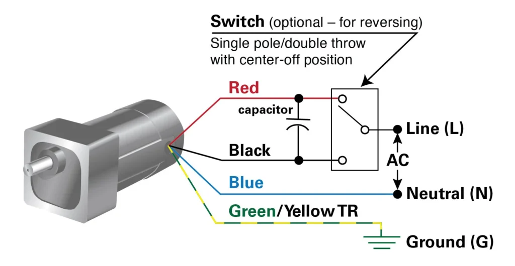
- Reversing motors: An SPDT switch can reverse the direction of a DC motor in its circuits by changing the polarity of the power supply to the motor.
- Selector switches: In a circuit, SPDT switches serve as selector switches that can choose between various inputs or outputs.
For example, a guitar pickup selector switch is typically an SPDT switch that allows the player to select between the bridge, neck, or both pickups.
- Control circuits: SPDT switches have the capability to activate or deactivate devices like relays or lights in control circuits.
- Audio applications: When it comes to audio equipment, SPDT switches serve the purpose of selecting between various signal paths or switching between different effects.
- Safety switches: SPDT switches can turn off machinery and industrial equipment when detecting a dangerous condition, making them useful as safety switches.
- Power supplies: In power supplies, SPDT switches find use in selecting between different voltage outputs or powering the supply on and off.
Overall, the versatility of the SPDT switch makes it a common component in a wide range of electrical and electronic devices.
Understanding the Components of an SPDT Switch
Acquiring an understanding of the components of an SPDT switch can be simplified by recognizing its internal structure.
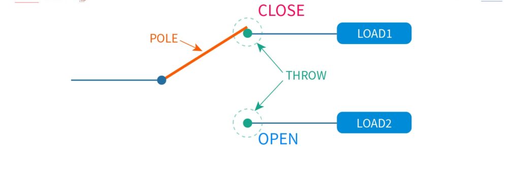
An SPDT switch consists of three terminals - one input terminal and two output terminals. For a switch to work properly, it must have an input terminal as its core. Its output terminals then flank this at either side for power transfer in both directions.
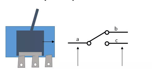
Inside the switch, there is a movable contact, which is typically a metal lever or arm that is connected to the switch's actuator or knob. Pivoting the actuator shifts an electrical connection from one output terminal to another, with a single input consistently maintained at all times.
Typically, the movable contact connects to a "common" contact located underneath the input terminal on the switch. Pivoting the actuator shifts an electrical connection from one output terminal to another, with a single input consistently maintained at all times.
The labeling of "normally open" (NO) and "normally closed" (NC) on the two output terminals of the switch allows for the distinction between a state of connection and one of disconnection.
In its resting or "off" position, the switch connects the common contact to the NC terminal, leaving the NO terminal unconnected to anything.
Operating the switch causes the common contact to disconnect from the NC terminal and instead connect to the NO terminal.
Overall, the components of an SPDT switch include the input terminal, two output terminals (NO and NC), the movable contact, and the common contact. A switch is like a bridge allowing electricity to flow from one terminal to the other, with its movable contact always connected as an intermediary.
Wiring an SPDT Switch in a Basic Circuit
Wiring an SPDT switch in a basic circuit is relatively straightforward. The following steps outline the process:
- Identify the input and output terminals of the circuit. The input terminal is where the power source or signal originator connects, and the output terminals are for connecting a load or device.
- Connect the input terminal of the circuit to the common contact of the SPDT switch. Typically, people solder a wire from the input terminal to the common contact on the switch to achieve this.
- Connect one of the output terminals (either the NO or NC terminal) to the load or device. To achieve this, people typically solder a wire from the output terminal to the device or load.
- Connect the other output terminal (either the NO or NC terminal) to the ground or to the negative terminal of the power supply. Soldering a wire from the output terminal to either a grounding point or negative power supply terminal is necessary for ensuring proper electrical connections and avoiding potentially hazardous situations.
- Test the circuit by operating the switch. By ensuring that the switch is in one position, you can connect the input terminal to either of the two output terminals. Alternatively, if you turn the switch into its other setting, then it will link the input terminal to a different output connection point.
Always ensure that the switch can handle both the power current and voltage to guarantee a safe and efficient electrical circuit. Failing to observe safety measures could result in serious injury or damage - so use caution when dealing with electricity! Furthermore, ensure that all cables are securely connected and there is no risk of a short circuit due to exposed wiring or loose connections.
SPDT Witch for Controlling Multiple Circuits
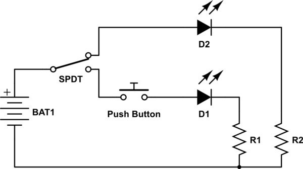
Wiring an SPDT switch for controlling multiple circuits involves connecting each circuit to one of the output terminals of the switch. Here's a step-by-step guide:
- Identify the circuits you want to control with the SPDT switch. These circuits should have separate input and output.
- Connect each circuit's input to the SPDT switch's common contact. You can do this by soldering wires from each circuit's input to the common contact of the switch.
- Connect the output of the first circuit to one of the output terminals of the switch. Solder a wire from the output of the circuit to either the normally open (NO) or normally closed (NC) terminal of the switch.
- Connect the output of the second circuit to the other output terminal of the switch. Solder a wire from the output of the circuit to the remaining terminal on the switch that was not used in step 3.
- If you have more circuits to control, repeat steps 3 and 4 for each additional circuit, connecting each circuit to a different output terminal of the switch.
- Test the circuits by operating the switch. With the flick of a switch, you can control which circuit gets powered. One position energizes one and deactivates others; toggle over to easily transfer power between circuits in an instant!
To ensure safe and efficient operation, be sure that your switch is properly rated for the voltage and current in each of your circuits. Pay special attention to secure connections between wires as any loose ends or exposed joints could lead to a hazardous short circuit. Stay alert when handling electricity!
Common Mistakes in Wiring an SPDT Switch
Following are the common mistakes to avoid when wiring an SPDT switch:
- Wiring the switch backward: An SPDT switch has two output terminals - the normally open (NO) and the normally closed (NC) - and it's important to connect the output terminals correctly. Make sure you understand which output terminal corresponds to which position of the switch before wiring it.
- Not properly securing the wires: Loose or unsecured wires can cause the circuit to malfunction or even cause a short circuit. Make sure all wires are properly secured and insulated.
- Using wires that are too thin: The wires used to connect the switch should be appropriate for the current and voltage of the circuit. In order to protect electrical components, make sure the wires you're using aren't too thin; excessive heat can cause undue damage. To ensure optimal performance and longevity of your circuit system, use a wire thicker than what's required for specifications.
- Using a switch that is not rated for the circuit: Be sure to check the voltage and current rating of the switch to ensure it is appropriate for the circuit. Installing a switch that is not suitable for the circuit can lead to dangerous malfunctions or even put you and your family at risk.
- Not testing the circuit before use: Before connecting any sensitive or expensive components to the circuit, it's important to test the circuit using a multimeter or other testing equipment. This can help you identify any issues with the wiring or connections before they cause damage.
- Not following safety procedures: Working with electricity can be dangerous, so it's important to follow proper safety procedures when wiring an SPDT switch. This includes turning off the power source before working on the circuit, wearing appropriate safety gear, and avoiding contact with exposed wires or components.
Troubleshooting Tips for SPDT Switch Wiring Issues
- Check the wiring: The first step in troubleshooting SPDT switch wiring issues is to check the wiring. Ensure all the wires are firmly connected to guarantee there is no exposed wiring or disconnected components.
- Check the switch position: If the switch is not functioning correctly, make sure that it is in the correct position. Incorrectly positioning a switch could have huge implications for the desired performance of your circuit; ensuring its correct placement is critical!
- Check the voltage and current: Always double-check that the electricity and amperage of the circuit are inside the parameters specified for your switch. If this is not done, there could be a higher probability of malfunction or full failure due to voltage or current levels beyond what your switch can handle.
- Check for shorts: If the circuit is not functioning correctly, check for shorts. A short circuit can cause the circuit to malfunction or even damage the switch or other components.
- Test the circuit: Use a multimeter or other testing equipment to test the circuit. This can help you identify any issues with the wiring or connections before they cause damage.
- Replace the switch: After you have ensured all wiring and connections are in order, tested the circuit, and made sure that the current is within the range appropriate for your switch; if it's still not working correctly, then a replacement of your switch might be necessary.
By following these troubleshooting tips, you can help identify and resolve SPDT switch wiring issues and ensure that your circuit functions as expected.
Conclusion
An SPDT switch is an essential component in circuitry, enabling the easy control of electrical currents to suit a variety of applications. It has three terminals - the common contact, the normally open (NO) contact, and the normally closed (NC) contact - and can be wired in various configurations to control one or multiple circuits. Wiring up an SPDT switch needs careful consideration of circuit parameters and safety precautions - always check the voltage/current range is compatible, and take sensible steps to protect against electrical dangers. If you experience issues with your SPDT switch wiring, troubleshooting tips such as checking the wiring, testing the circuit, and verifying the voltage and current can help identify and resolve the problem.

 NextPCB Capabilities
 PCB Assembly
 Layer Buildup
 SMD-Stencils
 PCB Design-Aid & Layout
 Mechanics
 Quality
 Drills & Throughplating
 Factory & Certificate
 PCB Assembly Factory Show
Certificate
PCB Assembly Factory Show
Certificate


 Surface

