
 NextPCB Capabilities
Printed Circuit Boards
NextPCB Capabilities
Printed Circuit Boards
 PCB Assembly
 Layer Buildup
 SMD-Stencils
 PCB Design-Aid & Layout
 Mechanics
 Quality
 Drills & Throughplating
 Factory & Certificate
 PCB Assembly Factory Show
Certificate
PCB Assembly Factory Show
Certificate
Support Team
Feedback:
support@nextpcb.com


The team is reengineering the FST09e prototype, the last electric PCB prototype developed by FST Lisboa, in order to transform it into a driverless car, the FST10d. The power supply of the FST09e consisted of an array of 2 DC-DC's in parallel connected to the High Voltage battery outputting a fixed voltage of 24 V. This solution was able to handle up to 400 W, not enough considering the new hardware necessary for the autonomous functionality, steering actuator, powerful computer to run the autonomous pipeline, etc. The team decided to develop a 24 V battery using lithium-polymer cells and for this reason, we also had to develop a Battery Management System to ensure the correct and safe functioning of the battery as well as to comply with the strict and extensive set of Formula Student rules.
Let's take a closer look into the development of the Low Voltage Battery Management System PCB!
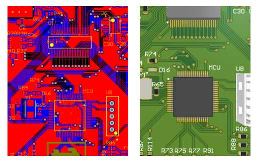
All the connections are routed carefully on the PCB and components placed, a process that takes the most amount of time and dedication!
After the layout is finished, a 3D preview of the final product can be seen:
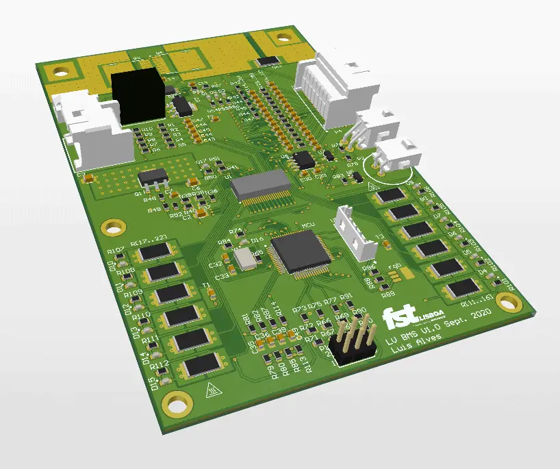
The final product meets all the specifications and beyond:
The Low Voltage Battery Management System or LV BMS as we call it, has three primary functions:
The circuit uses as a Micro Controlling Unit the STM32F405RGT7TR chip as STMicroelectronics. It offers plenty of IO's, up to 15 communication interfaces such as CAN and SPI, both needed for the project and RTOS (Real-Time Operating Systems) can be used to improve task scheduling, ensuring better program flow and event response.
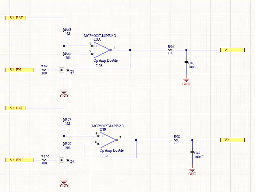
The battery was primarily intended for a 24 V application, having the possibility to connect up to 12 cells in series allowed the team to design a solution easily upgradable to a 48 V battery, standard in the automotive industry.
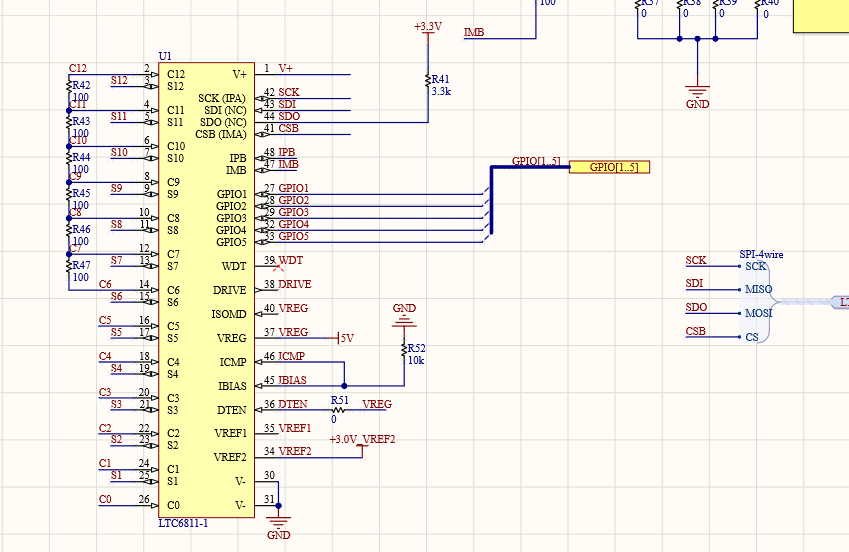
An LTC6811-1, 12 Channel Multicell Battery Monitor from Linear Devices is used for cell temperature and voltage measurement as well as cell balancing. This device communicates via SPI with the Micro Controlling Unit (MCU) in order to provide crucial information regarding the lithium battery cells.
Still, need help? Contact Us: support@nextpcb.com
Need a PCB or PCBA quote? Quote now


 Surface

