
 NextPCB Capabilities
Printed Circuit Boards
NextPCB Capabilities
Printed Circuit Boards
 PCB Assembly
 Layer Buildup
 SMD-Stencils
 PCB Design-Aid & Layout
 Mechanics
 Quality
 Drills & Throughplating
 Factory & Certificate
 PCB Assembly Factory Show
Certificate
PCB Assembly Factory Show
Certificate
Support Team
Feedback:
support@nextpcb.com


Standardize the PCB process design of the product, stipulate the relevant parameters of the PCB process design, so that the PCB design meets the technical specifications of manufacturability, testability, safety, EMC, EMI, etc., and build the product process, Technology, quality, and cost advantages.
This specification applies to the PCB process design of all electronic products, and is applied to but not limited to PCB design, PCB board process review, veneer process review and other activities. If the content of relevant standards and specifications before this specification conflict with the provisions of this specification, this specification shall prevail.
PCB board requirements
2. High-heat components should be placed in the air outlet or a location conducive to convection. In the PCB layout, consider placing high-heat components at the air outlet or at a location that is conducive to convection.
3. Higher components should be placed in the air outlet and should not block the air path
4. The placement of the radiator should be considered conducive to convection
5. Temperature-sensitive instruments should be kept away from heat sources. For heat sources whose temperature rises above 30°C, the general requirements are as follows:
If the required distance cannot be reached due to space reasons, a temperature test should be conducted to ensure that the temperature rise of the temperature-sensitive device is within the derating range.
Free PCB Design Analytics Software
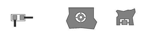
6. Large-area copper foil requires thermal insulation tape to be connected to the pad
In order to ensure good tin penetration, the pads of the components on the large-area copper foil are required to be connected to the pads with thermal insulation tape. The above high-current pads cannot use thermal insulation pads, as shown in the figure:
7. Heat dissipation symmetry of the pads at both ends of the reflowed 0805 and below 0805 chip components
In order to avoid the deviation and tombstone phenomenon of the device after reflow soldering, ground reflow soldered 0805 and below 0805 chip components
The pads at both ends should ensure the symmetry of heat dissipation, and the width of the connection between the pad and the printed wire should not be greater than 0.3mm (for asymmetric pads), As shown in the above figure.
Why Choose NEXTPCB Manufacturer
8. How to install high-heat components and whether to consider a radiator
Make sure that the installation method of high-heat components is easy to operate and weld. In principle, when the heating density of components exceeds 0.4W/cm3, single the lead legs of the components and the components themselves are not sufficient for heat dissipation. Measures such as heat dissipation nets and bus bars should be adopted to improve the overcurrent performance.
The legs of the bus bar should be connected at multiple points, and wave soldering after riveting or direct wave soldering should be used as much as possible to facilitate the installation. Matching and soldering; for the use of longer bus bars, the thermal expansion coefficient of the heated bus bar and PCB should not match when the wave crest is used. The resulting PCB is deformed.
In order to ensure easy operation of tin lining, the width of the tin channel should not be greater than or equal to 2.0mm, and the distance between the edges of the tin channel should be greater than 1.5mm.
Still, need help? Contact Us: support@nextpcb.com
Need a PCB or PCBA quote? Quote now


 Surface

