
 NextPCB Capabilities
Printed Circuit Boards
NextPCB Capabilities
Printed Circuit Boards
 PCB Assembly
 Layer Buildup
 SMD-Stencils
 PCB Design-Aid & Layout
 Mechanics
 Quality
 Drills & Throughplating
 Factory & Certificate
 PCB Assembly Factory Show
Certificate
PCB Assembly Factory Show
Certificate
Support Team
Feedback:
support@nextpcb.com


In this brief detailed short article, I will certainly reveal to you how to make a Line Fan Robotic Automobile. This task is based upon a microcontroller much more particularly Arduino.
The name Line fan name recommends a Totally Automated Auto. What adheres to an aesthetic line (More than likely white or Black) that is installed on any kind of flooring or any type of surface area.
This task is based upon a microcontroller much more particularly Arduino. Yet it is likewise feasible to create a line fan robotic without a microcontroller. However, there will certainly be restricted capability as well as the quit will certainly be less than any type of microcontroller-based car.
Due to the fact that the information handling power of the Microcontrollers is above straightforward Op-Amp ICs. This will certainly be a fundamental line fan robotic job record ppt.
This is an easy Microcontroller-based automobile. Let me inform you carefully just how things function. The automobile contains 2 IR sensing units.
This sensing unit detects the line shade is reflective or otherwise. The below representation suggests the surface area returns the light. In this instance, the reflective surface area is the White surface area. (The non-reflective surface area is the black lines just.) It suggests that black tracks do not mirror any kind of light back.
The working of the sensing unit is that it detects exists any type of reflective light returning or otherwise. after that just the sensing unit will certainly offer the outcome( Result 2 kinds. I will certainly talk about that later on). And also if there is no representation after that the IR sensing unit will certainly not offer any kind of result or simply put, the outcome will certainly be reduced.
Based upon these Low And High Result results the microcontroller can manage the cars and trucks.
The microcontroller provides the instructions to the cars and truck where to go and after that when to take turns (Left or Right) and also where to quit (I developed the code in such a way if the 2 sensing units obtain Black Surface area after that it will certainly inform the microcontroller to quit the cars and truck.).
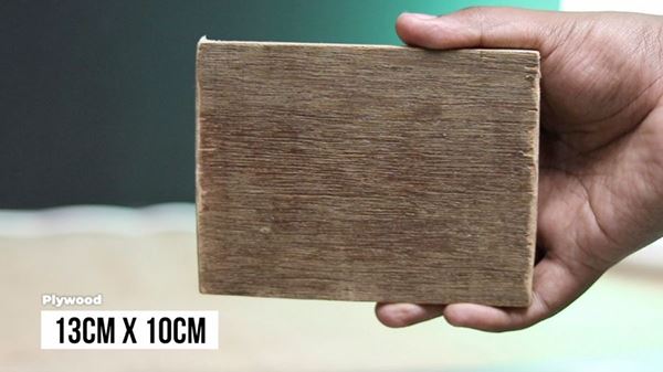
Action 1: First, we will certainly require a timber item as the cars and truck framework. Below I am utilizing 13CM x 10CM Plywood as the cars and truck framework. These measurements are perfect for making a TT Motor Car. You can additionally make use of a Polymer sheet or Premade framework likewise.
Action 2: Currently affix the electric motors on the 4 edges of the Plywood with a Glue weapon or any other adhesive. Make certain when you are connecting the electric motors that the electric motor placement ought to be proper. Or else, the vehicle will certainly not go straight.
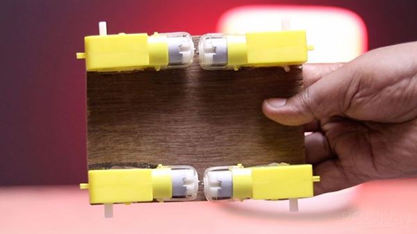
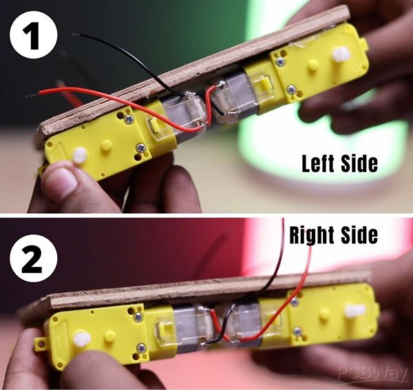
Action 3: Currently attach the TT Equipment Motors as revealed listed below. We will certainly link the electric motors in a criss-cross pattern. This is due to the fact that we need to make the automobile as if 2 side electric motor turns in exact same instructions in order to move forward Backwards as well as various other recognized instructions.
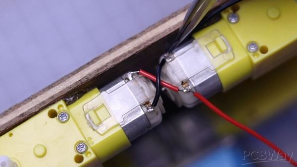
Action 4: After Attaching electric motors, the link ought to resemble this. Below I gave both side images for you to comprehend plainly what is taking place.
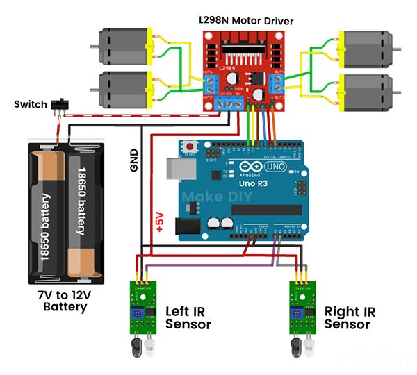
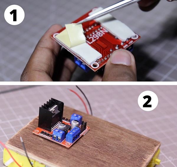
Action 5: Right here we are making use of an L298N Electric motor Motorist. I utilized double-sided tape for linking the L298N Electric motor motorist on the Plywood. You can additionally make use of Nut as well as screws for this.
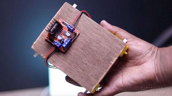
Action 6: After links, all cables will certainly appear like this.
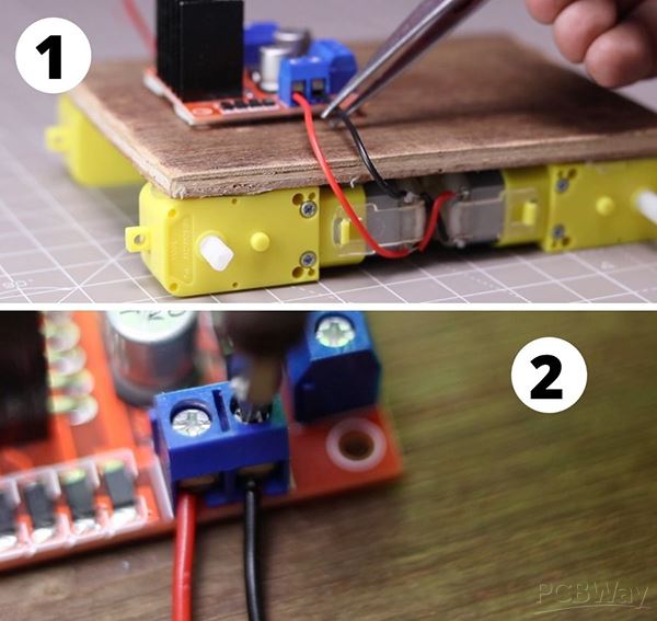
Keep in mind: After posting the code if the cars and truck is not entering the appropriate instructions or if it is turning in the wrong instructions after that simply alter the electric motor cables. As well as it will certainly simply function simply fine.Now link the electric motor cables with the L298N Electric Motor Vehicle Driver. And afterward Tighten up the electric motor vehicle driver cords. and also stay clear of any kind of sort of loosened link.
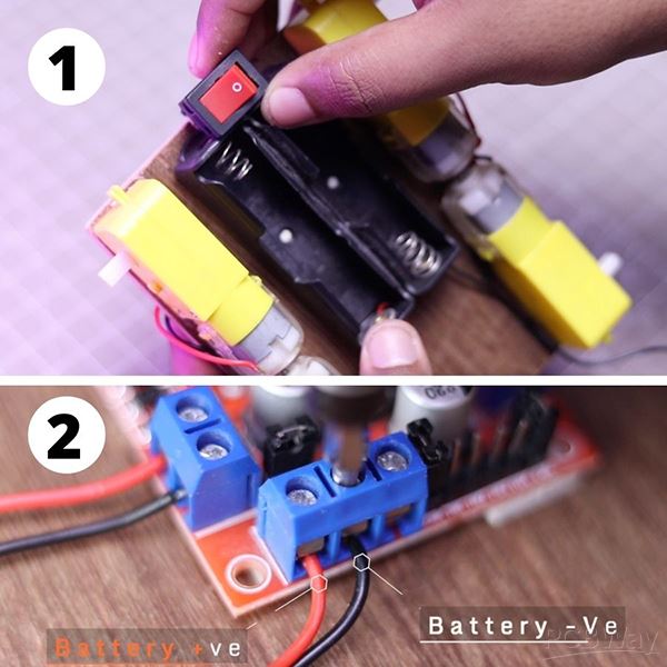
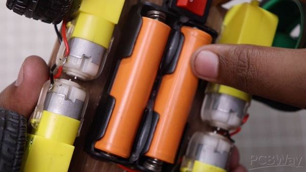
Action 7: For the Battery, I am making use of 2, 18650 batteries. This is fantastic for making this kind of auto. For attaching the batteries I am utilizing a 2s 18650 Battery owner. I likewise included a button for activating/ off the automobile. The battery cords will certainly be gotten in touch with the electric motor vehicle driver input cords. You can additionally plainly see where to link the battery cords.
Action 8: In this task, I am utilizing Arduino Uno as a Microcontroller. You can additionally make use of any other microcontroller as your dream. Yet because situation, the circuitry schematics will certainly be various. Next off, you need to get rid of the Jumper shorted adapters from the electric motor chauffeur for the following action of link.
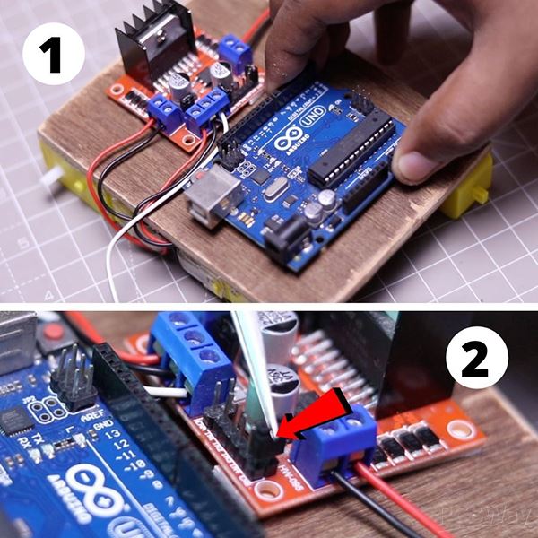
Action 9: Aware I have actually discussed the needed links for the electric motor chauffeur.
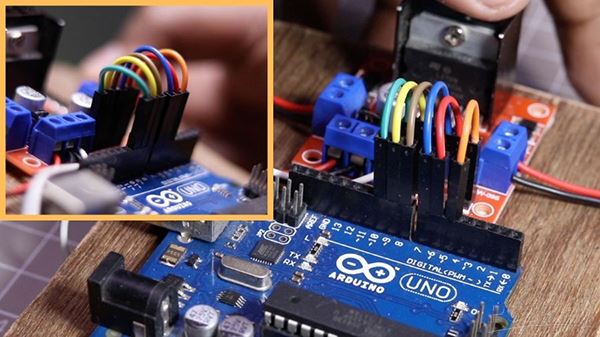
Action 10: Attach the IR Sensors as I received the image. After that attach the needed cables with the Arduino UNO. Simply Comply With the Circuitry Layout in the schematics. Currently, Publish the code to Arduino. Currently, we need to do the calibration for running the automobile.
Action 11: Attach the batteries to the vehicle and also switch on the button.
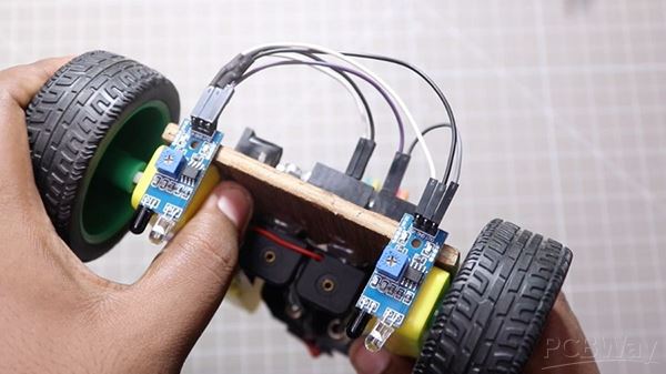
Action 12: (Sensing Unit Calibration) Prior to adjusting you need to link the wheels to the vehicle. You do not require to open up the serial display for calibration. It is simply hand-operated calibration. Below I made use of the digitalRead feature to separate in between Light and also Dark. So, the IR Sensing unit will certainly simply offer High/ Reduced as the Result. Area the vehicle on some High surface area. Right here I made use of a Leading cover of Spray Paint to position the auto on it for calibration. Below I am making use of the White surface area pair with a T-shaped line for calibration. (Those that are thinking of what I utilized for the T Forming. Below is the solution, This is basic Black Electric tape )
Location of the vehicle As I Received the picture. Currently, You prepare to adjust. Very first Revolve the 2 Potentiometers (Left & Right side sensing units both) complete Counter-clockwise.
So, the calibration procedure is bit much easier in this instance. Currently, you can activate the cars and trucks as well as put on the where you wish to adhere to as well as the vehicle will certainly adhere to the line.
/*

Code Name: Arduino Line Follower Robot Car

Code URI: https://circuitbest.com/category/arduino-projects/

Author: Make DIY

Author URI: https://circuitbest.com/author/admin/

Description: This program is used to make Arduino Line Follower Robot Car.

Note: You can use any value between 0 to 255 for M1_Speed, M2_Speed, LeftRotationSpeed, RightRotationSpeed.

Here 0 means Low Speed and 255 is for High Speed.

Version: 1.0

License: Remixing or Changing this Thing is allowed. Commercial use is not allowed.

*/


#define in1 9

#define in2 8

#define in3 7

#define in4 6

#define enA 10

#define enB 5


 int M1_Speed = 80; // speed of motor 1

 int M2_Speed = 80; // speed of motor 2

 int LeftRotationSpeed = 250; // Left Rotation Speed

 int RightRotationSpeed = 250; // Right Rotation Speed


 void setup() {


 pinMode(in1,OUTPUT);

 pinMode(in2,OUTPUT);

 pinMode(in3,OUTPUT);

 pinMode(in4,OUTPUT);


  pinMode(enA,OUTPUT);

  pinMode(enB,OUTPUT);


   pinMode(A0, INPUT); // initialize Left sensor as an input

   pinMode(A1, INPUT); // initialize Right sensor as an input


}


void loop() {


 int LEFT_SENSOR = digitalRead(A0);

 int RIGHT_SENSOR = digitalRead(A1);


if(RIGHT_SENSOR==0 && LEFT_SENSOR==0) {

  forward(); //FORWARD

}


 else if(RIGHT_SENSOR==0 && LEFT_SENSOR==1) {

  right(); //Move Right

 }


 else if(RIGHT_SENSOR==1 && LEFT_SENSOR==0) {

  left(); //Move Left

}


 else if(RIGHT_SENSOR==1 && LEFT_SENSOR==1) {

  Stop(); //STOP

 }

}


void forward()

{

      digitalWrite(in1, HIGH);

      digitalWrite(in2, LOW);

      digitalWrite(in3, HIGH);

      digitalWrite(in4, LOW);


        analogWrite(enA, M1_Speed);

        analogWrite(enB, M2_Speed);

}


void backward()

{

      digitalWrite(in1, LOW);

      digitalWrite(in2, HIGH);

      digitalWrite(in3, LOW);

      digitalWrite(in4, HIGH);


        analogWrite(enA, M1_Speed);

        analogWrite(enB, M2_Speed);

}


void right()

{

      digitalWrite(in1, LOW);

      digitalWrite(in2, HIGH);

      digitalWrite(in3, HIGH);

      digitalWrite(in4, LOW);


        analogWrite(enA, LeftRotationSpeed);

        analogWrite(enB, RightRotationSpeed);

}


void left()

{

      digitalWrite(in1, HIGH);

      digitalWrite(in2, LOW);

      digitalWrite(in3, LOW);

      digitalWrite(in4, HIGH);


        analogWrite(enA, LeftRotationSpeed);

        analogWrite(enB, RightRotationSpeed);

}


void Stop()

{

      digitalWrite(in1, LOW);

      digitalWrite(in2, LOW);

      digitalWrite(in3, LOW);

      digitalWrite(in4, LOW);

}
Easy troubleshoot if the auto is not entering the best instructions: If this occurs and also your automobile is not entering the best instructions after that you do not need to customize any kind of code. You need to simply alter the electric motor vehicle driver cords. Currently, your automobile will certainly enter the appropriate instructions.
All needed links are supplied to the cars and truck like Power In, L298N Electric Motor Vehicle Driver Pinout, Left IR sensing unit, as well as Right IR sensing unit pinout.
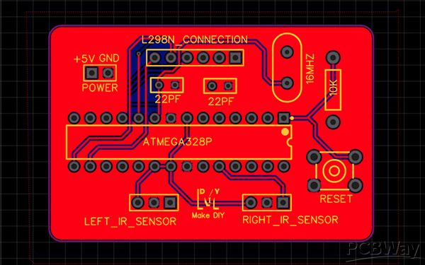
Right here I utilized Atmega328P Microcontroller. This IC is additionally made use of in Arduino Uno R3. So, we will certainly simply configure the Arduino UNO R3 and also eliminate the chip from UNO Board and also position it on the PCB. This will certainly provide the marginal want to the Vehicle.
Overall this is an excellent car and truck for enthusiasts. Ensure you do all the actions I have actually received the video clip. The rate of the automobile is reduced for complying with the line effectively. If you intend to accelerate the cars and trucks after that you can utilize IR Variety. Yet it is a subject for an additional video clip. Hope you individuals taken pleasure in by making this vehicle.
I have actually additionally supplied Just how to accelerate the automobile while mosting likely to straight lines and also angular turning in the code. Simply alter the rate specification according to your auto. Do not make the rate criterion excessive or else, the vehicle will certainly be unable to make any type of fast turning.
This is the only corn of the automobile. It is a terrific job for enthusiasts. You can make this for enjoyable tasks along with scientific research tasks.
Still, need help? Contact Us: support@nextpcb.com
Need a PCB or PCBA quote? Quote now


 Surface

