
 NextPCB Capabilities
Printed Circuit Boards
NextPCB Capabilities
Printed Circuit Boards
 PCB Assembly
 Layer Buildup
 SMD-Stencils
 PCB Design-Aid & Layout
 Mechanics
 Quality
 Drills & Throughplating
 Factory & Certificate
 PCB Assembly Factory Show
Certificate
PCB Assembly Factory Show
Certificate
Support Team
Feedback:
support@nextpcb.com


ZIF (no insertion pressure) port is a connector alternative for versatile published circuit (FPC) port accessory, which calls for extremely little, or perhaps no pressure for insertion. In the 1970s, ports began to appear with functions to allow absolutely no insertion connector. ZIF adapters are excellent for little centerline spacing demands, due to the fact that it is not sensible to make a bigger wire-to-board connect in such scenarios. With numerous pitch and also circuit dimension choices, ZIFs use very easy actuation and also protected wire retention in between the FFC-FPC as well as the adapter terminals.
ZIF layout is generally discovered in a lot of adaptable circuit applications, consisting of customer electronic devices, company tools, safety systems, clinical gadgets and also tools, display screens, and also interactions, which add to the 4 benefits of ZIF connect.
ZIF adapters are a preferred selection for versatile circuit add-ons. The selection enables a smooth technique that makes use of the adaptability nature of the versatile circuit quite possibly. Many adapters are created for either 1.0 mm or 0.5 mm pitch, nevertheless smaller sized much more thick patterns are likewise offered.
A ZIF port resembles a card side port for PCBs. The port itself frequently approves a 0.3 mm (12mil) thick flex circuit and also the cable television is kept in the area by rubbing or in some even more extreme cases, by a breeze down pressure alleviation. The distinction is that an inflexible PCB as soon as linked into an adapter, is really secure. The versatile circuit on the other hand is by its nature adaptable.
After the dimension of the port has actually been picked there are a couple of points to think about prior to delving into your versatile circuit style. With the circuit course straight right into the port? Will it make a sluggish soft bend right into the adapter? Or will it make a hard-sharp bend as a result of the absence of physical room? Every one of these situations has actually been made use of thoroughly for many years as well as a lot of the problems with each have actually been solved. There are constantly posting likely to be brand-new applications that test our style's effectiveness, however, if you comply with the guidelines that comply within a common fashion, you'll have the ability to deal with any type of circumstance that occurs.
Do not endanger below. The size and also its resistance is the first thing that will certainly create sorrow in any type of ZIF style. Any kind of concession on the resistance will certainly enable the circuit to move about in the adapter triggering aggravating recurring shorts or even worse yet, not enable the cord to suit the adapter in all.
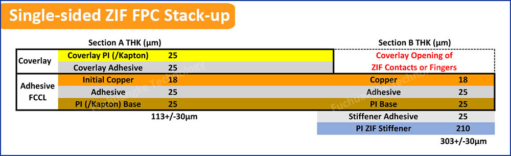
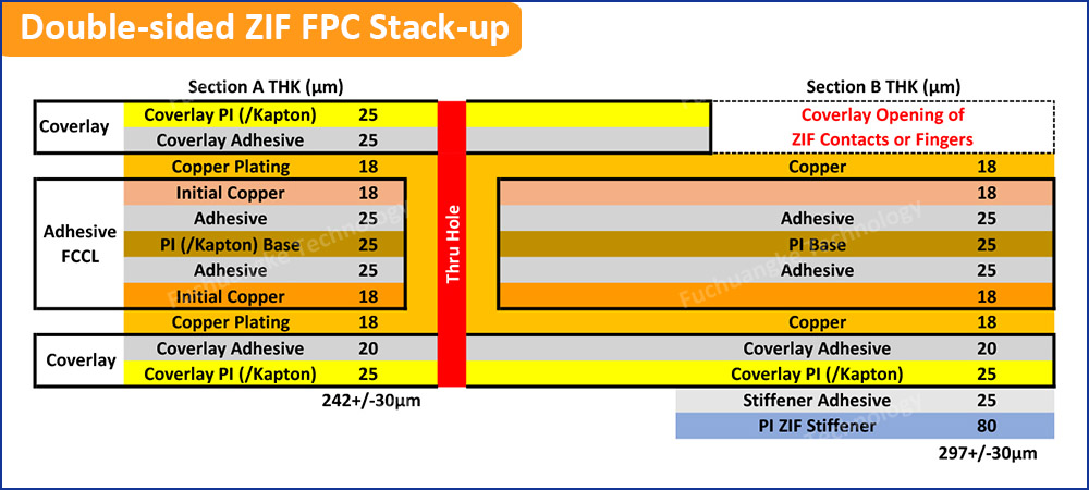
One of the most typical density spec for ZIF ports is 0.3 mm (12mil). This does not match the typical density of adaptable circuits. So, we need to usually include a polyimide or polyester support under the ZIF port pattern to produce the appropriate density regularly. As you can see in the number 1 (Single-sided ZIF FPC Stack-up) as well as number 2 (Double-sided ZIF FPC Stack-up) listed below, the density of the polyimide ZIF support was ended deliberately. This permits the density to be gotten used to the building of the adaptable PCB, whether it's a single-sided circuit as is portrayed over or a double-sided or multilayer flex circuit. In the numbers listed below, the density of the polyimide support will certainly be changed upon the adaptable circuit density to fulfill the density demand of 0.3 mm+/ -0.03 mm (12mil+/ -1 mil). The flex PCB density demand of ZIF ports requires us to do some estimation in order to fulfill the requirements with the products offered. In this instance we have 2 selections as well as the total density can be readjusted with the polyimide density or the sticky density.
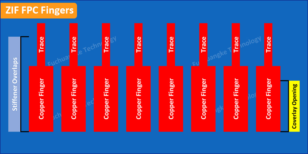
Those people that have actually created flex circuits for any kind of amount of time understand the positioning of the copper traces about the bend locations of the circuit is crucial information. Additionally, we understand that we can not merely align sides on top of each other and also anticipate toughness. In this instance, we'll have a coverlay available to reveal the copper fingers for the ZIF port and also a support to manage the correct density. If we align the support side with the overlay side with the trace to the pad joint, we will certainly likely see cracks in the trace at the pad joint. One of the most durable styles requires the pad to overlap the overlay opening and also the ZIF support to overlap the pad/trace joint. This permits the circuit to be placed without the worry of busted traces from imbalance throughout insertion. It additionally secures the circuit in vibrant applications or those times when a sharp bend is required to place the flex right into the port. See number 3 (ZIF FPC Fingers) listed below.
Still, need help? Contact Us: support@nextpcb.com
Need a PCB or PCBA quote? Quote now


 Surface

