
 NextPCB Capabilities
Printed Circuit Boards
NextPCB Capabilities
Printed Circuit Boards
 PCB Assembly
 Layer Buildup
 SMD-Stencils
 PCB Design-Aid & Layout
 Mechanics
 Quality
 Drills & Throughplating
 Factory & Certificate
 PCB Assembly Factory Show
Certificate
PCB Assembly Factory Show
Certificate
Support Team
Feedback:
support@nextpcb.com


Nothing is more fascinating than watching an electrical circuit turn an LED on and off. Creating a light strobe is simple, with a suitable drive circuit. Any DIY store will have what you need. This article focuses on two easy ways of DIY strobe light construction such as transistor based method and timer IC 555 based methods. During this article, you will be able to learn many variations of the strobe light controllers. Moreover, this article presents DIY strobe light controllers based on their power usage, such as, AC voltage powered diy strobe controller, DC voltage powered DIY strobe controllers. However, most of the circuits operate at 12v (12v strobe light circuits)
You've come to the right site if you want to learn more about DIY strobe lights and how they operate.
A stroboscopic gadget produces strobe effects. Simply put, an LED strobe light emits intense bursts of light. It creates a steady, powerful burst of light. The blue and red overhead lights on a police car are a great illustration of a strobe light.

Strobe lights are useful as a self-defence tool in addition to lighting. They currently play a significant role in flashlights. Typical light sources for strobe kits include LEDs, halogen lights, and xenon flash lamps. Additionally, they are the standard blinking mechanism in clubs and party venues. Strobes have a quick recycling time and an output range for a complete flash of 100 to 1,000 watts. Above all, special lighting equipment emits a quick flash of LED strobe light that produces stroboscopic effects. They are also used for industrial, commercial, and medicinal purposes.
The terms "strobe flash" and "strobe light" are frequently misunderstood by electronic hobbyists. The strobe flash of light is just as attention-grabbing. As a result, they serve several purposes as entertainment equipment. The flash energy is a key distinction between strobing and flashing, though. However, a strobe light flashes and the manner of the flash is undoubtedly distinct.
Additionally, stronger and producing extremely brief bursts of light, strobe flashes are used. A strobe light has a pulse-switching light in the meanwhile. Unlike flashing, the strobe light double flash pattern is tailored to produce sharp blinking light flashes (2 x 20ms per second). While flashes clearly have a brief flash duration, compared to strobes, they also have a longer recycle time and less accurate colour.
An electronic component known as a transistor can use in circuits to amplify or switch electrical impulses or power, making a vast range of electronic devices possible. Two PN diodes linked back to back form a transistor. It features emitter, base, and collector terminals as its three terminals. The fundamental principle of a transistor is that it enables you to modify the intensity of a much smaller current flowing through a second channel to regulate the current flow through one channel.
The transistor is an amplification component. It is available in valuable items like hearing aids, one of the earlier devices people used before transistors. Hearing aids use a small microphone to capture noises from your environment and transform them into different electric currents. Additionally, microphones are sent into a transistor, which enhances a tiny loudspeaker so that you may hear an improved version of the sounds around you.
Moreover, transistors serve as switches. A tiny electric current can cause a significantly more significant current to flow through one of a transistor's parts and vice versa.
All computer chips operate in the same manner. For instance, a memory chip has hundreds of transistors that may all be individually turned on or off. Every transistor has two possible states, allowing it to independently store the integers 0 and 1. With billions of transistors and as many characters and digits, a chip can hold many zeros and ones.
This article introduces a few circuit constructions depending on the components.
All these circuits went through a testing process by our circuit moderators to ensure their operation. Therefore, the users can select any circuit design and start building to their liking.
Components List:
As in Circuit 1, the circuit uses 12v DC voltage. Therefore this circuit is a 12v strobe light circuit. However, in order to use 5v power input, it is advisable to not use the 330-ohm Resistor due to the voltage drop.
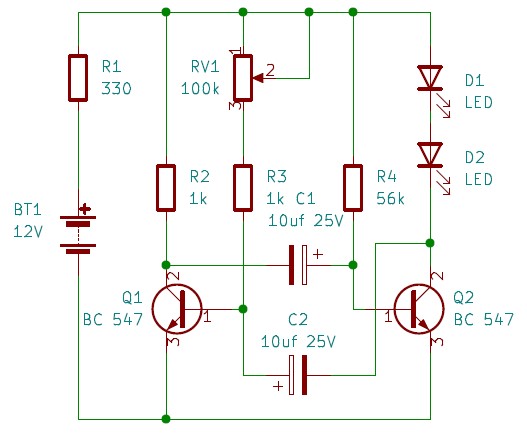
Circuit 1
The 100k preset can change the frequency of the lights by switching to the corresponding resistance. 12v strobe light circuit can be further modified as follows.
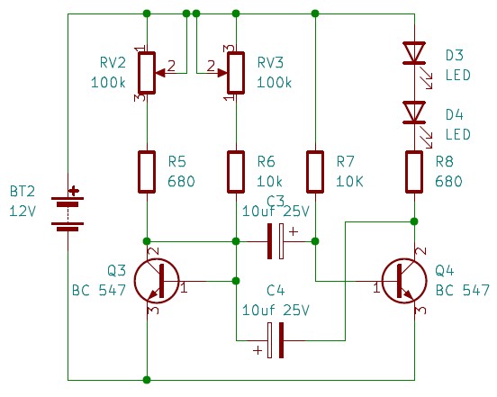
Circuit 2
Components List:
Here a torch bulb is using as the light source, as shown in the circuit below. Here it is noticeble that there are minor modifications in the 12v strobe light circuit .
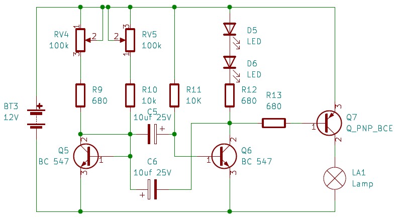
Circuit 3
Components List:
This 12V strobe light circuit use a TB122 PNP transisor. This makes the strobe process easier. However, the 100k presets need to adjust appropriately for better results.
Modifying the above 12v strobe light circuit a little further allows laser light to use instead of LEDs or Motorcycle bulbs, as shown in Citcuit 4.
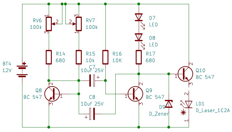
Circuit 4
Components List:
Laser lights are very famous in recent times. Most DIY projects tend to involve at least one laser light into their projects. The above circuit demonstrates a straightforward on how to use a laser as a DIY strobe light. In few modifications can be clearly noticed. A Zener diode can use depending on the laser maximum voltage specification. The value of the Zener diode can be found using the laser diode's datasheet. The reason behind using the Zener diode is the laser diode's protection. The zener diode ensures correct current is passing through it so it won't receive too much light to cause any harm. The zener operates by providing a constant current and a constant voltage.
The primary distinction between AC and DC voltages is that the polarity of the wave in an AC voltage varies with time, and it always remains the same in a DC voltage. All the above circuits designed to use DC voltages. The following circuit design shows how to use an AC lamp as a DIY strobe light. This circuit has two main changes. There is a Triac involvement, and the circuit uses AC and DC voltages. The DC voltage operates as the strobe's primary circuit while the AC voltage drives the AC lamp using the Triac.
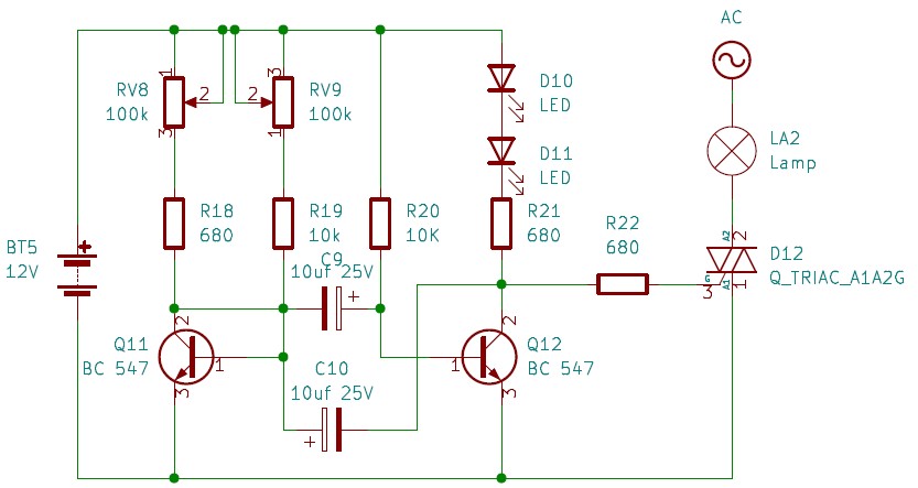
Circuit 5
Components List:
In this section of the article, we introduce two DIY strobe controllers using 555 timer IC.
The 555 is an astable multivibrator in this High Intensity LED Strobe Circuit. On the output side, it will provide square pulses that are constant. The LED will on and off by these pulses. By altering the potentiometer connected to the circuit, we may change the pace at which the LED blinks. This time is dependent on the duty cycle of the square wave. Several applications use 555 IC, some of which are as follows.
Moreover, due to the easy implementation and handling, 555 timer placed in many ways by DIY projects.
This section of the article introduces a simple but effective method to use 555 IC to design a DIY strobe controllers.
Circuit 6
Components List:
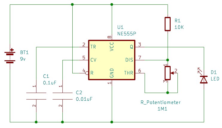
The above mentioned components are required for the DIY strobe controller using 555 timer IC. Timer IC 555 placed with few variable and fixed resistors, as shown in the 12v strobe light circuit diagram. This 12v strobe light circuit power up with a 12 v DC power supply. If you use an external power source, set the voltage to 12 volts. Feed wire connectors are also necessary to connect the individual Resistor and capacitor to the 555 timer device. The connection of the circuit can explaine as follows. First, connect the positive terminal of the power supply, in this case, the 12v DC power supply, to the timer IC 555 pins 4 and 8. Then connect the negative terminal of the power supply, which can also named as the ground terminal in this circuit, to pin 1 of the IC 555 timer. Then, the capacitor terminals can connect, as shown in the 12v strobe light circuit diagram. Next, the variable Resistor and the fixed Resistor placed between six and seven pins of the timer IC 555. The threshold capacitor, which is 0.1uF, is connecting between the ground and pin 2 of the IC 555 timer. 0.01uF capacitor has to connect via pin 5 of timer IC 555 and the ground supply. Then, between pin 7 of the timer IC and the battery holder, the 10k Resistor must be placed. As the final step, the output pin of the IC 555 timer (pin 3) can use to connect the LEDs, as shown in circuit 6.
The 555 timer IC will function as an astable multivibrator in this design. At the output, it will continuously create square pulses. Anode and Cathode are the two terminals of the 1-watt white LED. The duration of these waves, which turn the LED on and off, is determined by the square wave's duty cycle. By adjusting the potentiometer's knob, we can alter the LED's blinking rate. Use an LED heat sink with the LED if you wish to operate this circuit continuously.
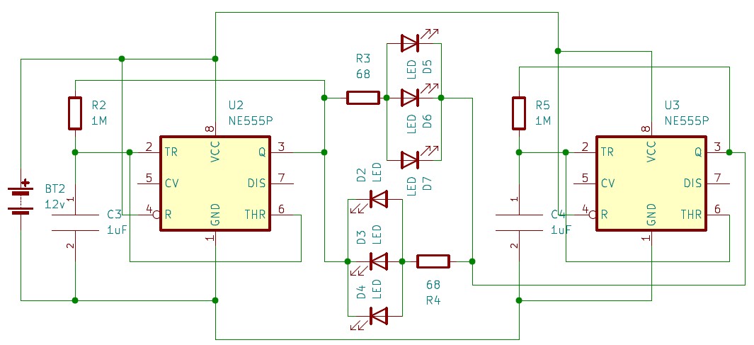
Circuit 7
We utilized two identical astable circuits tuned at various frequencies to create this police strobe-style flashing LED circuit. Because the first 555 timer IC has a big capacitor, switching the output takes longer. The output is toggled extremely quickly by the second 555 timer IC since it has a smaller capacitor. When there is a positive voltage at the anode and a negative voltage at the Cathode, the first group of LEDs (the red LEDs) goes ON. This scenario occurs when the outputs of the first and second 555 timer ICs are both ON simultaneously. When the outputs of the first and second 555 timer ICs are turned off simultaneously, the above scenario occurs. Therefore, only the first group of LEDs have a chance of going ON when the output of the first 555 timers IC is ON. They blink at the rate at which the second 555 timer IC toggles the output. Similar to how only the second group of LEDs have a chance of going ON when the first 555 timer IC toggles the output, and they flash at the same rate as the second 555 time IC. This cycle can be repeated endlessly to provide a significant LED flasher effect that resembles the flashing lights on police cars. The construction of the DIY strobe controller is shown in circuit 7.
This article introduces a few methods to implement a DIY strobe controller. Here, the article forcus on desiging transistor-based and 555 timers IC based circuits. Under the transistor-based method, there are five variations according to the type of light source. However, each strobe light circuit diagram was an extension of the primary transistor-based DIY light strobe. There are two 12v strobe light circuit implementations under the 555 timers IC-based light strobe construction. The first one used a single LED to implement the strobe effect, and the second was to implement the police light effect. Two 555 timer IC combined to use in the police car light circuits. However, there are many other methods of implementing a DIY strobe controllers. Suppose you are a hobbyist and have the craving to dig deeper in the field of electronics and circuit designing. In that case, this article is not the end.
Still, need help? Contact Us: support@nextpcb.com
Need a PCB or PCBA quote? Quote now


 Surface

