
 NextPCB Capabilities
Printed Circuit Boards
NextPCB Capabilities
Printed Circuit Boards
 PCB Assembly
 Layer Buildup
 SMD-Stencils
 PCB Design-Aid & Layout
 Mechanics
 Quality
 Drills & Throughplating
 Factory & Certificate
 PCB Assembly Factory Show
Certificate
PCB Assembly Factory Show
Certificate
Support Team
Feedback:
support@nextpcb.com


The prerequisite for circuit problem calculation is to correctly identify the circuit and figure out the connection relationship between the various parts. For more complex circuits, the original circuit should be simplified to an equivalent circuit for analysis and calculation. There are many ways to identify circuits, and ten methods are introduced with specific examples.
The characteristic of the series-parallel circuit is that the current in the series circuit does not bifurcate, and the potential of each point is gradually reduced. In the parallel circuit, the current bifurcates, and the two ends of each branch are at equal potential, and the voltage between the two ends is equal. Identifying circuits based on the characteristics of series and parallel circuits is one of the most basic ways to simplify circuits.
example 1. Try to draw the equivalent circuit shown in Figure 1.
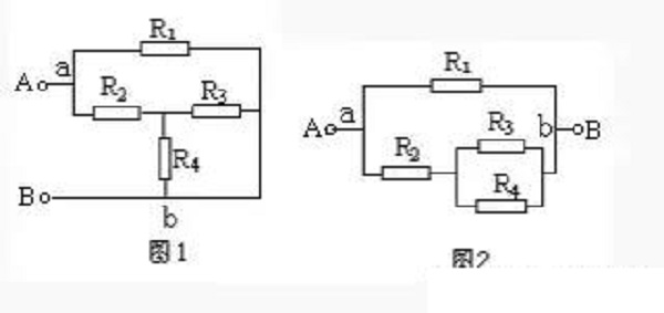
Solution: Suppose the current flows in from terminal A, diverges at point a, merges at point b, and flows out from terminal B. The potentials of the branches a—R1—b and a—R2—R3(R4)—b are gradually reduced, and the voltages between points a and b of the two branches are equal. Therefore, it is known that R3 and R4 are connected in parallel and connected in series with R2, and then In parallel with R1, the equivalent circuit is shown in Figure 2.
This can often be done when connecting circuits in the laboratory. The unimpeded wire can be extended or shortened, or turned over, or turned over a branch, and the two ends of the branch remain stationary when turned; the lead can also be removed from it. Sliding along other wires on the node where it is located, but not over the component. This provides a way to simplify the circuit. We call this method the telescopic flip method.
Example 2. Draw the equivalent circuit of Figure 3.
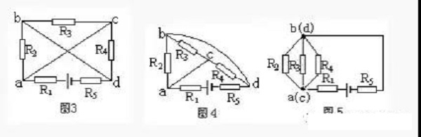
Solution: First shorten the wire connecting node a and c, and turn the wire connecting node b and d to the outside of the branch R3-C-R4, as shown in Figure 4.
Then shrink the wire connecting nodes a and C to a point, shrink the wire connecting nodes b and d to a point, and connect R5 to the wire extension line of node d (Figure 5). It can be seen that R2, R3 and R4 are connected in parallel, and then connected in series with R1 and R5, and connected to the power supply.
Current is the core of the analysis circuit. Starting from the positive pole of the power supply (passive circuits can assume that the current flows from one end to the other end). Follow the direction of the current, and go around the external circuit through the resistors to the negative pole of the power supply. All the resistors that flow through in turn without bifurcation are In series connection, all resistors that have bifurcated currents are connected in parallel.
Example 3. Try to draw the equivalent circuit shown in Figure 6.
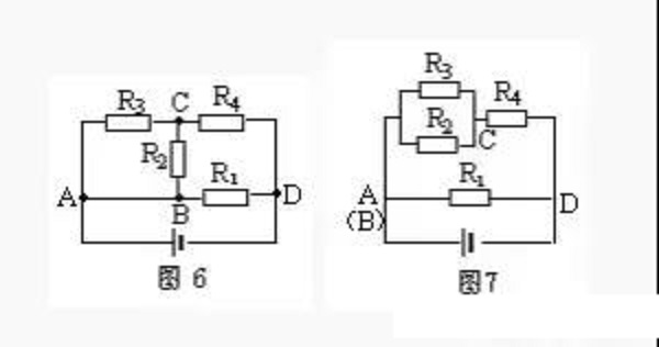
Solution: The current flows from the positive pole of the power supply through point A and is divided into three paths (the AB wire can be reduced to one point), and it patrols for a week through the external circuit, and flows into the negative pole of the power supply from point D. The first road goes directly to point D through R1, the second road goes to point C through R2, and the third road goes to point C through R3. Obviously, R2 and R3 are connected in parallel between two points AC. The two and three currents converge at point c and reach point D through R4. It can be seen that R2 and R3 are connected in parallel and connected in series with R4, and then connected in parallel with R1, as shown in Figure 7.
In more complex circuits, points with equal potential can often be found, and all points with equal potential can be reduced to one point or drawn on a line segment. When there are non-power components between two equipotential points, they can be removed and ignored; when a branch has neither power nor current, this branch can be cancelled. We call this simple ratio circuit method the equipotential method.
Example 4. As shown in Figure 8, knowing that R1=R2=R3=R4=2Ω, find the total resistance between A and B.
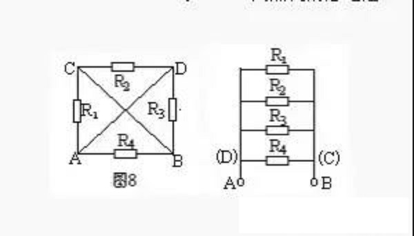
Solution: Imagine connecting the two points A and B to the positive and negative poles of the power supply for analysis. The potentials of A and D are equal, and the potentials of B and C are also equal. Draw two line segments respectively. Resistor R1 is connected to A and C, that is, to A and B; R2 is connected to C and D, that is to B and A; R3 is connected to D and B, that is Connected to the two points A and B, and R4 is also connected to the two points A and B. It can be seen that the four resistors are all connected in parallel between the two points A and B (Figure 9). Therefore, PAB=3Ω.
A node is the meeting point of several branches in a circuit. The so-called branch node method is to number each node (agreement; the positive pole of the power supply is the first node, from the positive pole to the negative pole of the power supply, the nodes passed in order are 1, 2, 3...), and the branch starting from the first node Road, draw to the negative pole of the power supply. There may be multiple branches (regulation: different branches cannot pass through the same resistor repeatedly) to reach the negative pole of the power supply. The drawing principle is to draw the branch with fewer nodes first, and then the branch with more nodes. Then, according to this principle, draw the branch starting from the second node. By analogy for the remaining times, finally the remaining resistors are drawn according to the positions of their two ends.
Example 5. Draw the equivalent circuit shown in Figure 10.
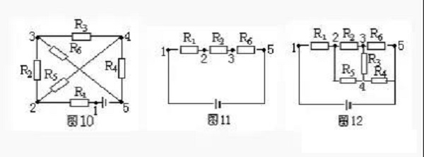
Solution: In Figure 10, there are five nodes 1, 2, 3, 4, and 5. According to the principle of branch node method, from the positive pole of the power supply (the first node), there are two branches with a small number of nodes: R1, R2, R5 branch and R1, R5, R4 branch. Take one of the R1R2 and R5 branches and draw it as shown in Figure 11.
Starting from the second node, there are two branches that can reach the negative pole, one is R5, R4, the number of nodes is 3, the other is R5, R3, R5, the number of nodes is 4, and it is not advisable to have R6 repeated. Therefore, the branches R5 and R4 should be drawn again, and finally the remaining resistance R3 should be drawn, as shown in Figure 12.
The geometric deformation method is based on the characteristics that the wires in the circuit can be extended, shortened, rotated or translated arbitrarily, geometrically deform a given circuit, further determine the connection relationship of the circuit components, and draw an equivalent circuit diagram.
Example 6. Draw the equivalent circuit of Figure 13.
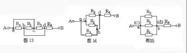
Solution: shorten the wire of the ac branch and geometrically deform the circuit to get Figure 14. Then reduce ac to a point and bd to a point. It is obvious that R1, R2, and R5 are connected in parallel, and then connected in series with R4 (Figure 15).
According to the characteristics of series and parallel circuits, in a series circuit, if any resistor is removed and no current flows through the other resistors, these resistors are connected in series; in a parallel circuit, if any resistor is removed, the other resistors still have current through them, then these resistors are connected in series. It is connected in parallel.
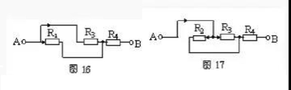
Still taking Fig. 13 as an example, suppose that the current flows in from end A and flows out from end B. First remove R2. From Fig. 16, it can be seen that R1 and R3 have current flowing. After removing the resistor R1, it can be seen from Figure 17 that R2 and R3 still have current flowing through it. Similarly, when the resistance R3 is removed, R1 and R2 also have current through the characteristics of the parallel circuit. R1, R2 and R3 are connected in parallel, and then connected in series with R4.
Let the current flow out of the positive pole of the power supply, without repeating the principle of passing through the same element, if there are several paths that flow back to the negative pole of the power supply, there are several independent branches. The remaining resistors that are not included in the independent branch are supplemented according to the positions of their two ends. When applying this method, select the independent branch to include the wire.
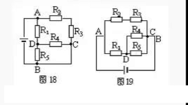
Example 7. Draw the equivalent circuit of Figure 18.
Solution 1: Choose A—R2—R3—C—B as an independent branch, A—R1—R5—B as another independent branch, and connect the remaining resistor R4 between D and C, as shown in Figure 19.
Number each node in a known circuit and mark it with 1, 2, 3... numbers in the order of potential from high to low (the node connected to the positive pole of the power supply has the highest potential, and the node connected to the negative pole of the power supply has the lowest potential, equal potential Use the same number for the nodes and merge them into one point). Then re-arrange the nodes according to the level of electric potential, and then connect each component to the corresponding two nodes, then the equivalent circuit can be drawn.
Example 8. Draw the equivalent circuit shown in Figure 22.
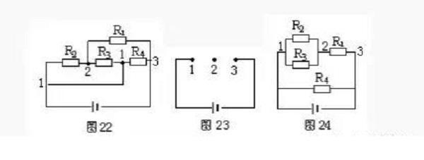
untie. Node number: as shown in Figure 22.
Node arrangement: Arrange 1 and 23 nodes in a straight line at intervals, as shown in Figure 23.
Component homing: Comparing to Figure 22, connect R1, R2, R3, and R4 to the arranged 1, 2 to obtain the equivalent circuit as shown in Figure 24.
Scheme 2: Select A—R1—D—R4—C—B as an independent branch, and then arrange the positions of R2, R3, and R5, respectively, to form the equivalent circuit diagram 20.
Solution 3: Select A—R2—R3—C—R4—D—R5—B as an independent branch, and then connect R1 between AD and the wire between C and B, as shown in Figure 21, the result It is still impossible to intuitively judge the series-parallel relationship of the resistors, so the unimpeded wire must be included when selecting the independent branch.
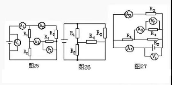
Solution: First remove the ammeter, replace it with a wire, and then remove the voltmeter as an open circuit, as shown in Figure 26. Then add the ammeter and voltmeter to the corresponding positions in the circuit according to Figure 25, as shown in Figure 27.
Still, need help? Contact Us: support@nextpcb.com
Need a PCB or PCBA quote? Quote now


 Surface

