
 NextPCB Capabilities
Printed Circuit Boards
NextPCB Capabilities
Printed Circuit Boards
 PCB Assembly
 Layer Buildup
 SMD-Stencils
 PCB Design-Aid & Layout
 Mechanics
 Quality
 Drills & Throughplating
 Factory & Certificate
 PCB Assembly Factory Show
Certificate
PCB Assembly Factory Show
Certificate
Support Team
Feedback:
support@nextpcb.com


Circuit boards display a wide array of characteristics, configurations, and dimensions. They can be categorized by frequency, materials employed, or the number of layers incorporated. Typical PCB types include Rigid, Flex, and Rigid-Flex. Rigid PCBs are more frequently encountered, while flex and rigid-flex versions are less common. Nevertheless, a select group of skilled manufacturers can produce these specialized PCBs upon request. This article provides a brief explanation of rigid-flex PCB, its applications, and various factors to choose from while selecting this PCB.
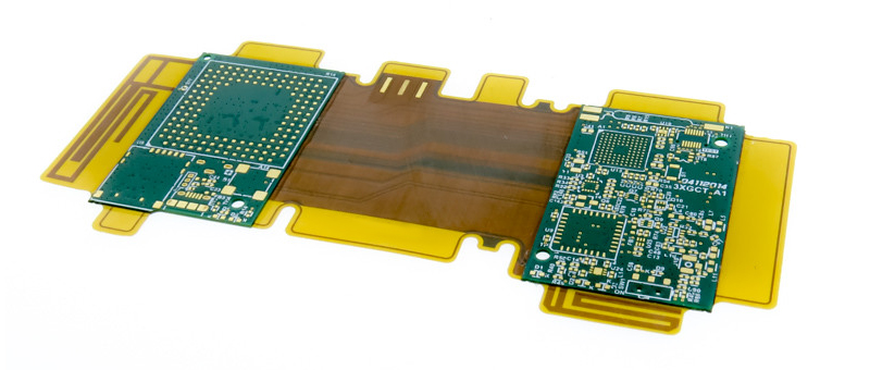
Rigid-flex printed circuit boards combine the technologies of both flexible and rigid boards. They typically comprise several layers of flexible circuit substrates connected to one or multiple rigid boards, either externally or internally, depending on the application's design requirements. The flexible substrates are intended for constant flexing and are often shaped into a curve during production or installation.
Designing rigid-flex boards is more complex than creating standard rigid boards, as they are developed in a 3D space, providing increased spatial efficiency. This three-dimensional design approach allows designers to bend, twist, and fold the flexible board substrates to achieve the desired form for the final application's packaging.
When it comes to flexible PCB or rigid-flex PCB, there are numerous layer stacks to choose from. The most basic option involves a single flex region with two copper layers that are constructed on a flexible substrate material such as polyimide. This type of flex region can be directly integrated into a rigid-flex PCB stackup or utilized on its own. In the case of a rigid-flex PCB, the coverlay film is fused to the prepreg during lamination to allow for the assembly of FR-4 stiffener regions onto the flex ribbon.
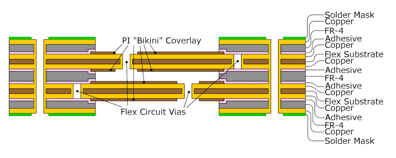
Typically, a rigid-flex stack-up comprises at least one flexible layer pair positioned between rigid sections. For instance, double-sided flexible PCBs laminated with rigid sections and layers of pre-preg are the most commonly designed rigid-flex boards, as illustrated in the figure above.
It is worth noting that the stiffener sections utilize prepreg to bond to the flex section in all these arrangements. Nonetheless, the layer stack depicted above is not limited to just one internal copper layer and two rigid FR-4 layers. Multiple rigid layers can be stacked on each side of the flex region, and the FR-4 layers on each end can have varying layer counts since they will be laid up and press laminated individually.
|
Feature |
Rigid-Flex PCBs |
Traditional PCBs |
|
Design Complexity |
High, considering the integration of rigid and flex parts and how bending affects circuits. |
Lower, typically involving only rigid materials. |
|
Material Selection |
Requires a combination of rigid (e.g., FR4) and flexible (e.g., Polyimide PI) materials. |
Mainly uses rigid materials, such as FR4, aluminum, etc. |
|
Manufacturing Process |
More complex, needing special processes to combine rigid and flexible sections with precise alignment. |
Relatively simpler, as it involves only rigid materials, with more mature and standardized processes. |
|
Application Areas |
Suitable for complex applications needing flexible connections or high space utilization, like wearable devices, foldable phones. |
Broadly used across various consumer electronics, industrial equipment, etc., with a wider range of applications. |
|
Cost |
Higher, due to more complex design and manufacturing processes, as well as higher material costs. |
Lower, thanks to mature, standardized manufacturing processes and relatively lower material and production costs. |
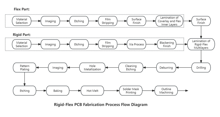
Due to the hybrid nature of rigid-flex PCBs, which combine elements of both FPC (Flexible Printed Circuits) and traditional rigid PCBs, the production of rigid-flex PCBs necessitates facilities equipped for both FPC and PCB manufacturing. Initially, electronic engineers design the circuit and form factor of the flexible part of the board based on specific requirements. Subsequently, these designs are sent to factories capable of producing rigid-flex PCBs. There, CAM (Computer-Aided Manufacturing) engineers process and plan based on the provided files. Following this, the required FPCs are produced on FPC production lines, while PCBs are manufactured on PCB lines. After manufacturing, according to the electronic engineer's specifications, the FPC and PCB components are seamlessly laminated together using a lamination press. This process is followed by several detailed steps to finally produce the rigid-flex PCB. A critical stage in this process, given the complexity and detail-oriented nature of rigid-flex PCBs, involves a thorough inspection before shipment. This is essential due to the high value of these boards, ensuring that no losses are incurred by either the supplier or the customer due to product issues.
Below is a brief production flow diagram for rigid-flex PCBs:
Multi-Layer Integration: Combining rigid and flexible layers in a single design requires careful planning to ensure proper alignment and connectivity.
Signal Integrity: Maintaining signal integrity across different materials and layers can be complex due to variations in impedance and potential signal loss.
Material Compatibility: Ensuring that materials used for both rigid and flexible sections are compatible in terms of thermal expansion, adhesion, and mechanical properties.
Durability: Selecting materials that can withstand repeated flexing without degrading or breaking.
Precision Fabrication: High precision is needed to manufacture rigid-flex PCBs, especially for fine-pitch components and complex geometries.
Layer Stack-Up: Managing the layer stack-up and ensuring proper lamination and bonding between rigid and flexible sections.
Higher Costs: Rigid-flex PCBs are generally more expensive to design and manufacture compared to standard rigid PCBs due to the complexity and specialized materials involved.
Prototyping Expenses: The costs associated with prototyping can be high, given the need for precision and potential multiple iterations.
Heat Dissipation: Effective thermal management is crucial to prevent overheating, especially in high-density designs where heat can accumulate.
Mechanical Stress: Ensuring the design can withstand mechanical stress, especially in the flexible regions which undergo bending and flexing.
Comprehensive Testing: Rigid-flex PCBs require extensive testing to ensure reliability, including mechanical, thermal, and electrical testing.
Component Placement: Accurate component placement is critical, especially in the transition areas between rigid and flexible sections.
Solder Joint Reliability: Ensuring reliable solder joints in areas that may experience mechanical stress or flexing.
Addressing these challenges requires a careful balance of design expertise, material science knowledge, and advanced manufacturing techniques to produce reliable and high-performing rigid-flex PCBs.
Still, need help? Contact Us: support@nextpcb.com
Need a PCB or PCBA quote? Quote now


 Surface

