
 NextPCB Capabilities
Printed Circuit Boards
NextPCB Capabilities
Printed Circuit Boards
 PCB Assembly
 Layer Buildup
 SMD-Stencils
 PCB Design-Aid & Layout
 Mechanics
 Quality
 Drills & Throughplating
 Factory & Certificate
 PCB Assembly Factory Show
Certificate
PCB Assembly Factory Show
Certificate

Support Team
Feedback:
support@nextpcb.com


Electronic circuits called current limiting circuits restrict the flow of current through specific components or loads. They safeguard vulnerable components from harm caused by too much current and support the circuit in working safely and dependably.
To avoid permanent damage to components and ensure safety, limiting the current flowing through a component or load in electronic circuits is crucial. Excessive current can cause overheating of the component and lead to failures in other circuit components, posing a potential safety hazard.
Current-limiting circuits protect circuits from overcurrent by detecting and regulating current flow. There are many different types of current-limiting circuits, each with its own advantages and disadvantages. The choice of the circuit depends on the specific needs of the application. Whether you are designing a PCB from scratch or refining an existing layout, understanding current limiting is fundamental to reliable electronics design.
Before diving into circuit types, it is worth clarifying a common point of confusion: the difference between a current limiting resistor and a current limiting circuit.
A current limiting resistor is the simplest, most cost-effective passive element used to restrict current. It works on Ohm's Law — by placing a resistor in series with a load, the resistor drops voltage proportionally to the current, capping the maximum current the load can draw. This approach is common in LED applications, pull-up/pull-down networks, and low-power signal circuits.
A current limiting circuit, on the other hand, is a broader category that includes any active or passive design intended to hold current below a set threshold. This includes transistor-based regulators, op-amp feedback loops, dedicated ICs, and more. Active current limiting circuits respond dynamically to load changes, making them suitable for power supplies, motor drivers, and battery chargers where simple resistors would be too lossy or insufficiently precise.
The right choice depends on your load characteristics, efficiency requirements, and design budget. The sections below cover both approaches in detail.
There are different categories of current-limiting circuits available for restricting the flow of current through a specific circuit board component or load. These categories include:
Current Limiting Resistors: A current limiting resistor restricts the current flow through a load by placing a resistor in series with it. The efficacy of the circuit while safeguarding against the excessive current flow depends on the precise selection of resistor value.
Current Limiting Diodes: Inserting a diode, known as a current-limiting diode, in the circuit along with the load helps limit the current flow through the circuit. When the current surpasses a specific threshold, the diode starts conducting, which puts a limitation on the current.

Current Limiting Transistors: Placing current-limiting transistors in series with the load is a way to help control the amount of current that flows through a circuit. It limits the current by controlling the voltage across the load.
Current Limiting ICs: The designers made what is called a current-limiting integrated circuit (IC), which limits the flow of electricity through a circuit. These ICs use different techniques like sensing the current passing through the load and adjusting the load's voltage to restrict the current.
There are different types of current limiting circuits that have their own pros and cons. For instance, current limiting resistors are cost-effective and straightforward but might not be efficient and may generate extra heat. On the contrary, current limiting ICs are more precise and efficient, albeit more complicated and expensive.
Calculating the correct current limiting resistor value is one of the most common tasks in circuit design. Whether you are protecting an LED, a microcontroller GPIO pin, or a sensor, the calculation follows the same principle: Ohm's Law combined with Kirchhoff's Voltage Law.
The standard formula for a series current limiting resistor is:
R = (Vs – Vf) / If
Where:
Suppose you are connecting a standard red LED to a 5 V Arduino GPIO pin. The LED datasheet specifies:
Step 1 — Identify supply voltage: Vs = 5 V
Step 2 — Apply the formula:
R = (5 V – 2.0 V) / 0.02 A
R = 3.0 V / 0.02 A
R = 150 Ω
Step 3 — Select nearest standard resistor value: The E24 series includes 150 Ω exactly. If your calculation falls between standard values, always choose the next higher value to keep current slightly below, not above, the rated limit.
Step 4 — Verify power dissipation:
P = I² × R = (0.02)² × 150 = 0.06 W (60 mW)
A standard 1/8 W (125 mW) resistor is more than sufficient. For higher-current designs, always verify power rating to prevent resistor failure. If you are planning your PCB component placement, it is good practice to apply a derating margin of at least 50%.
| Supply Voltage (Vs) | LED Vf | Target If | Calculated R | Nearest Standard R |
|---|---|---|---|---|
| 3.3 V | 2.0 V (Red) | 20 mA | 65 Ω | 68 Ω |
| 5 V | 2.0 V (Red) | 20 mA | 150 Ω | 150 Ω |
| 5 V | 3.2 V (Blue/White) | 20 mA | 90 Ω | 100 Ω |
| 12 V | 2.0 V (Red) | 20 mA | 500 Ω | 510 Ω |
| 12 V | 3.2 V (Blue/White) | 20 mA | 440 Ω | 470 Ω |
LEDs are among the most current-sensitive components in electronics. Unlike resistors, an LED's forward voltage is relatively fixed, but its current rises steeply with even a small voltage increase. Without a current limiting resistor — or a dedicated LED driver — even a small overvoltage can destroy an LED within seconds.
An LED does not have a linear V-I relationship. Once it reaches its forward voltage threshold, current increases exponentially. A current limiting resistor "flattens" this curve by absorbing the excess voltage, keeping the LED operating safely at its rated current. For single LEDs driven from a microcontroller (3.3 V or 5 V), a series resistor is the standard solution. For multi-LED strips, high-power LEDs, or constant-brightness requirements, a dedicated LED driver circuit or constant-current IC is preferred.
R (Ω) = (Supply Voltage – LED Forward Voltage) ÷ LED Current (A)
Common LED forward voltages by color:
When LEDs are connected in series, their forward voltages add up. The formula becomes:
R = (Vs – n × Vf) / If
Where n is the number of LEDs in the chain. For example, driving three blue LEDs (Vf = 3.2 V each) from a 12 V supply at 20 mA:
R = (12 – 3 × 3.2) / 0.02 = 2.4 / 0.02 = 120 Ω
For high-power LED designs integrated into a custom PCB, NextPCB's thermal management guidelines are a valuable resource — heat dissipation is especially critical when driving high-brightness LEDs.
Current limiting circuits identify the quantity of current flowing through a specific component or load and decrease the load's voltage to maintain the current within the limit. The technique used to restrict the current will vary based on the particular kind of current-limiting circuit in use.
The circuit connects the current-limiting resistor in series with the load. We choose the resistance value to restrict the current to a safe level by limiting the voltage drop across the resistor. Ohm's law states that a resistor's voltage drop is proportional to its current.
A current-limiting diode circuit includes a diode in series with the load. Instead of a fixed resistance, the diode conducts when the current exceeds a threshold. This increases the voltage drop across the diode, thereby limiting the current flowing through the load.
A transistor in these circuits regulates the voltage across a load to keep the current safe. The transistor conducts when the current surpasses a certain quantity, reducing load voltage and current.
A current-limiting IC circuit uses various techniques to sense the amount of current flowing through the load and then adjust the voltage across the load to limit the current. These techniques include sensing the voltage drop across a sense resistor, employing feedback control circuits, or adopting other specialized methods.
Current limiting is a fundamental protection mechanism in virtually every modern power supply. Whether it is a bench power supply, a switching regulator, or a linear regulator, the ability to cap output current protects both the supply itself and the load from damage during fault conditions such as short circuits or inrush events.
Most laboratory and industrial power supplies operate in two modes:
The crossover between CV and CC modes is controlled by the current limiting circuit inside the power supply. A classic implementation uses an op-amp comparator monitoring a current sense resistor (shunt) in series with the output. When the sensed current reaches the set point, the op-amp takes control of the output transistor from the voltage loop, clamping current to the limit.
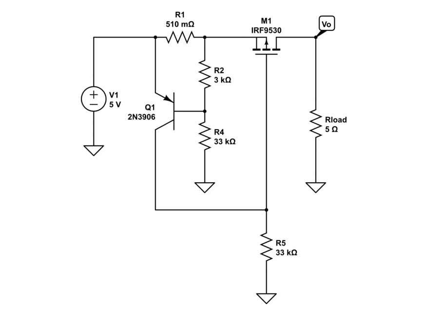
A simple discrete DC current limiter can be built around a BJT transistor and a sense resistor:
This approach is widely used in linear regulator designs and bench power supplies. For switching power supplies (SMPS), current limiting is typically implemented in the PWM controller IC, which monitors peak or average inductor current and skips switching pulses when the limit is reached.
Large capacitive loads draw a very high current spike the moment power is applied. This inrush current can trip fuses, damage rectifier diodes, or cause voltage sags on shared rails. Solutions include:
Careful PCB layout practices — such as keeping high-current paths short and wide — are equally important to avoid parasitic inductance that can worsen inrush transients.

The use of these circuits comes with both advantages and disadvantages that depend on the particular circuit type and the application requirements. Here are some pros and cons of using current limiting circuits.
Current limiting circuits are applicable in electronic circuits to restrict the flow of current through a load. They have various applications, including the following:
While discrete transistor-based circuits are educational and useful in simple designs, dedicated current limiter ICs offer higher precision, adjustability, and integration. Here is an overview of the most widely used current limiting ICs and devices that engineers reach for in professional designs.
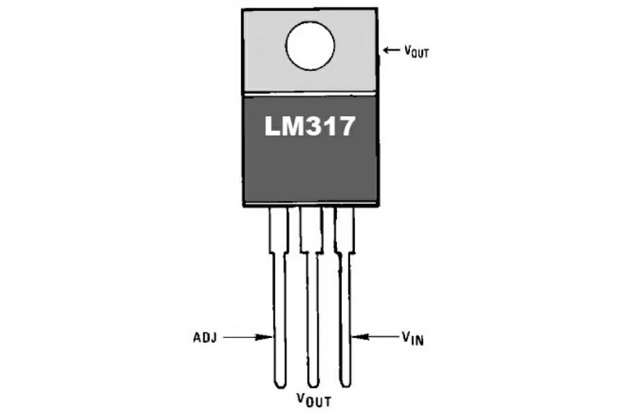
The LM317 is one of the most versatile and widely available ICs. In a current limiter configuration, an external resistor between the output and adjustment pins sets the current limit. The output pin maintains approximately 1.25 V above the adjustment pin, so the current limit is:
Ilimit = 1.25 V / R_set
For example, for 500 mA limiting, R_set = 1.25 / 0.5 = 2.5 Ω. The LM317 is a go-to solution for simple, low-cost constant current designs up to about 1.5 A.
These ICs are designed for hot-swap and inrush current control in backplane and power distribution applications. They feature adjustable current limit thresholds, an enable/disable input, and a fault output flag. Ideal for systems where boards are inserted into live backplanes.
A high-side current sense IC that outputs a voltage proportional to the load current. Often used in combination with an op-amp or a MOSFET for a complete current limiting feedback loop. Its advantage is a very low voltage drop compared to discrete solutions.
Targeted at USB port protection, the MCP1812 offers a fixed current limit with automatic latch-off on overcurrent or thermal shutdown. A popular choice for USB hub and interface designs.
While technically a current sense amplifier rather than a limiter on its own, the INA240 is the front-end of choice for high-side current monitoring in motor drives and power stages. Its output feeds into a comparator or MCU ADC to implement software-defined current limiting.
| Device | Type | Max Current | Adjustable? | Best For |
|---|---|---|---|---|
| LM317 | Linear regulator | 1.5 A | Yes | Simple CC loads, LED drivers |
| TPS2490 | Hot-swap controller | Up to 10 A (ext. FET) | Yes | Power distribution, backplanes |
| MCP1812 | Current limiting regulator | 1 A | No (fixed) | USB port protection |
| ZXCT1009 | Current monitor | N/A (sense only) | Via external R | High-side current feedback |
| INA240 | Current sense amp | N/A (sense only) | Via MCU | Motor drives, power stages |
When selecting a current limiter IC for a production SMT assembly design, factor in package availability, lead time, and thermal performance within your PCB layout. NextPCB's engineering team can assist with component sourcing during PCBA projects.
A fixed current limit suits many applications, but there are scenarios — such as multi-chemistry battery chargers, variable bench supplies, or test equipment — where an adjustable current limiter is essential. Several approaches exist, depending on complexity and precision requirements.
The simplest adjustable design replaces the fixed sense or bias resistor with a potentiometer. Turning the potentiometer changes the voltage threshold at which the limiting transistor begins to conduct, altering the current limit. This is an analogue, manual solution — inexpensive but not remotely controllable.
A more precise approach uses an op-amp in a negative feedback loop:
This topology provides excellent accuracy and is easy to control digitally using a DAC output from a microcontroller. It forms the basis of most precision bench power supplies.
For microcontroller-based designs, a PWM output filtered through an RC network generates an analogue reference voltage for the op-amp current control loop. This allows software-defined current limits that change dynamically — useful for multi-stage battery chargers (bulk → absorption → float) or adaptive motor current limiting based on speed or temperature feedback.
When implementing adjustable current limiting in a PCB design, pay special attention to the sense resistor footprint. The resistor must have a low temperature coefficient of resistance (TCR) to maintain accuracy across operating temperatures. Four-terminal (Kelvin) sense resistors are recommended for currents above 1 A to eliminate the error from PCB trace resistance. NextPCB's PCB design guide covers trace width and current capacity recommendations in detail.
To ensure that the current limiting circuit functions properly various factors must be taken into account during the design process. Here are some relevant factors to consider when designing a current limiting circuit:
Understanding schematic symbols and circuit diagram conventions for current limiting elements is essential for reading and creating electronics schematics accurately.
In schematics, a current limiting resistor is represented by the standard resistor symbol — a rectangle (IEC standard) or a zigzag line (ANSI/IEEE standard) — placed in series with the load. It is typically labeled "R" with a subscript (e.g., R1, RLIM) and has the resistance value annotated nearby.
A current-limiting diode (also called a current regulator diode or CRD) uses the standard diode symbol — a triangle pointing in the direction of conventional current flow, with a vertical bar at the tip. Some schematics annotate CRDs with "CRD" or "CLR" to distinguish them from signal or rectifier diodes.
A complete current limiter schematic typically includes:
When reviewing or creating current limiter schematics as part of a PCB project, tools such as KiCad, Altium, or EasyEDA support full schematic-to-layout workflows. NextPCB integrates with EasyEDA for direct PCB ordering, streamlining the path from schematic design to manufactured board.
To sum up, current limiting circuits are crucial in protecting electronic circuits from overcurrent conditions that could harm the load or circuit components. They are available in various types, each intended for particular applications, and they function by restraining the flow of current passing through the load.
Current limiting circuits are an essential element of electronics, protecting high-performance components while improving the reliability and efficiency of their operations. To maximize performance, careful selection must be made to weigh factors like load type, current/voltage ratings, response time temperature range and cost - thus ensuring reliable protection for your circuit's most valuable assets.
A current limiting circuit is an electronic circuit that restricts the maximum current that can flow through a load or component. It protects sensitive devices from damage caused by overcurrent conditions such as short circuits, inrush events, or unexpected load changes. Current limiting circuits range from a simple series resistor to complex active designs using transistors, op-amps, or dedicated ICs.
A current limiter works by monitoring the current flowing through a circuit and intervening when it exceeds a set threshold. Passive limiters such as resistors and diodes inherently drop more voltage as current rises, naturally capping the current based on Ohm's Law. Active limiters use a feedback loop where a sense element measures current and a control element reduces the supply voltage to the load, bringing current back within the set limit.
The simplest way to limit current in a circuit is to place a resistor in series with the load, using R = (Vs – Vload) / Ilimit to calculate the value. For more precise or efficient limiting in power supplies, battery chargers, or motor controllers, use an active circuit with a sense resistor, a transistor or MOSFET, and a feedback network. Dedicated current limiter ICs such as the LM317 in constant-current configuration provide the simplest route to adjustable, accurate current limiting.
A resistor limits both, but in a series circuit it is primarily used to limit current. By Ohm's Law (V = I × R), a series resistor drops a voltage proportional to the current flowing through it. This voltage drop reduces the voltage available to the load, which in turn limits the current the load can draw. The resistor itself does not sense or regulate — it passively impedes current by its fixed resistance value.
In a DC circuit, current flow is limited by the total resistance and impedance of the circuit according to Ohm's Law (I = V / R). This includes the load resistance, any series resistors, the internal resistance of the source, and parasitic resistances of wires and PCB traces. Additional current limiting can be introduced by active components such as transistors, ICs, or thermal protection circuits that reduce voltage when current rises above a threshold.
A fuse is a one-time overcurrent protection device that physically destroys itself to break the circuit when current exceeds a rated value, and must be replaced after operation. A current limiting circuit, by contrast, is a continuous, self-recovering protection mechanism. It does not break the circuit; instead, it reduces the current to a safe level and restores normal operation once the fault is cleared. Current limiting circuits are preferred in applications where frequent overcurrent events are expected or where manual fuse replacement is impractical.
Key factors for choosing a current limiting device include: the maximum current to be limited, the supply voltage range, whether the limit needs to be fixed or adjustable, efficiency requirements (passive resistors are lossy; active ICs are more efficient), response time (active circuits respond faster), and the operating temperature range. For low-current signal applications, a simple resistor suffices. For power applications, a transistor circuit or dedicated IC such as the LM317 or TPS2490 is more appropriate. Always consult the component datasheet and verify thermal performance within your PCB layout.
Designing a current limiting circuit is only half the journey — bringing it to life as a reliable, production-quality PCB is the other half. NextPCB offers comprehensive PCB Assembly (PCBA) services covering everything from component sourcing and SMT placement to soldering, inspection, and functional testing.
Still, need help? Contact Us: support@nextpcb.com
Need a PCB or PCBA quote? Quote now




