
 Surface


Zhang

 NextPCB Capabilities
Printed Circuit Boards
NextPCB Capabilities
Printed Circuit Boards
 PCB Assembly
 Layer Buildup
 SMD-Stencils
 PCB Design-Aid & Layout
 Mechanics
 Quality
 Drills & Throughplating
 Factory & Certificate
 PCB Assembly Factory Show
Certificate
PCB Assembly Factory Show
Certificate
Support Team
Feedback:
support@nextpcb.com


Table of Contents
Heat accumulation constitutes a critical challenge throughout the modern electronic design process. As devices continue to trend toward smaller, denser, and more powerful configurations—whether in high-power LED lighting, high-speed processors, or complex automotive electronic control units—power density on circuit boards is climbing at an unprecedented rate. This concentration of heat poses the greatest threat to electronic product reliability and performance. If heat cannot be effectively expelled, component life will be sharply reduced, performance will degrade, and catastrophic system failure may occur.
Thermal conductivity (k) is a fundamental material property that quantifies the rate at which heat is transferred through a substance; the low k value of FR-4 presents the primary obstacle to efficient cooling.
For a long time, FR-4 (fiberglass-reinforced epoxy laminate) has been the dominant substrate material in PCB manufacturing. It is cost-effective, possesses excellent mechanical and electrical properties, and is flame retardant (“FR” stands for Flame Retardant). FR-4 excels as an insulator, ensuring electrical isolation. However, this very strength as an electrical insulator has become the major bottleneck in modern high-density design: FR-4 is inherently inefficient at thermal conduction.
For professional hardware design teams, the core objective is not to abandon FR-4—given its unmatched value proposition—but to accurately understand its thermal limitations and implement advanced design and manufacturing processes to circumvent these restrictions. This article analyzes the mechanism of thermal conduction in FR-4 from both material science and engineering practice perspectives, and provides a series of quantitatively validated engineering solutions to ensure circuit boards remain cool and reliable even in the most demanding applications.
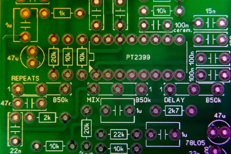
FR-4 is a composite material primarily consisting of two components: woven E-glass fiberglass cloth (providing mechanical strength and structure) and thermoset epoxy resin (providing electrical insulation). Once cured, the epoxy resin forms a rigid, chemically resistant matrix with excellent electrical insulation properties, which is its fundamental advantage as a PCB substrate.
However, it is this characteristic as an electrical insulator that establishes FR-4’s main thermal limitation. A fundamental difference exists between thermal conductivity and electrical conductivity: metals like copper can rapidly conduct heat (thermal conductivity k ≈ 400 W/(m·K)), but FR-4’s epoxy resin matrix is designed to resist current flow, which inherently makes it resistant to heat flow as well.
The thermal conductivity k value of standard FR-4 is very low, typically ranging only from 0.3 to 0.4 W/(m·K). In contrast, copper’s thermal conductivity is approximately 1000–1300 times greater than FR-4 (the exact ratio depends on the FR-4 formulation and operating temperature). This means that without auxiliary thermal structures, heat has difficulty being effectively transferred away through the FR-4 substrate, especially in high-power density areas.
Analyzing FR-4’s thermal performance must incorporate the concept of anisotropy. This means FR-4 exhibits different thermal conductivity values in different directions, a variation determined by its layered structure of glass fibers and resin.
In-Plane Conduction (X–Y axis): Heat flows along the length and width of the PCB (parallel to the fiberglass cloth). The thermal conductivity in this direction commonly ranges from 0.3 to 0.4 W/(m·K). In certain high-glass content or specific material formulations, the in-plane conductivity may be slightly higher (up to ~0.6–0.8 W/(m·K)). Designers should rely on the specific values provided in the chosen material’s data sheet. This offers the potential to use large copper areas for lateral heat spreading.
Through-Plane Conduction (Z-axis): Heat flows vertically through the thickness of the PCB (from the surface to internal or bottom layers). This is the path with the poorest thermal performance, where the thermal conductivity is typically as low as 0.29 W/(m·K).
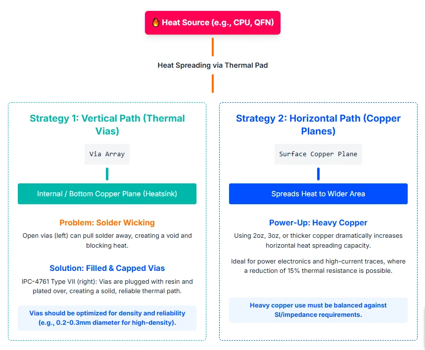
This anisotropic characteristic is central to PCB thermal design. Since heat generated by surface-mount devices must first pass vertically through this Z-axis insulating layer (the most resistive path) before reaching internal or bottom heat-dissipation planes, effective thermal management strategies must focus on bypassing this vertical bottleneck—for instance, by shortening the thermal path (reducing board thickness, which must be weighed against mechanical strength, signal integrity, and manufacturing feasibility) or by providing low-resistance bypasses (using copper thermal vias).
| Property | Typical Value | Design Significance |
|---|---|---|
| Standard Through-Plane Conductivity (Z-axis) | 0.29 – 0.40 W/(m·K) | Vertical heat-flow bottleneck; primary obstacle to component cooling. |
| Standard In-Plane Conductivity (X–Y axis) | 0.34 – 0.81 W/(m·K) | Determines the efficiency of copper-layer heat spreading. |
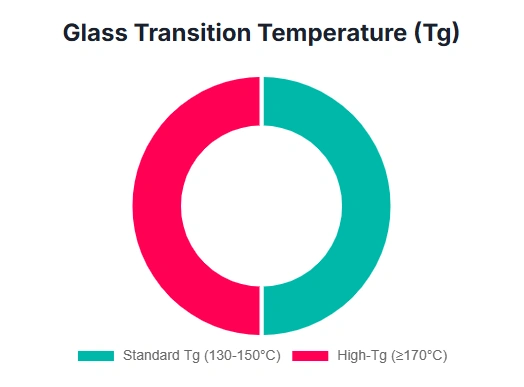
| Glass Transition Temperature (Tg) | Standard ≈ 130–150 °C; High Tg ≥ 150–170 °C | Rigidity-to-rubbery transition; high Tg suits lead-free soldering and high thermal-stress environments. |
In high-power applications, heat accumulation leads to a sharp reduction in component lifespan. Component life typically decreases according to the Arrhenius law as temperature rises (a common empirical rule suggests lifespan approximately halves for every 10 °C increase in temperature). To ensure long-term reliability, the design goal is generally to control temperatures in critical areas to within 60 °C to 70 °C, with specific limits defined by the component data sheets.
The key metric for evaluating a material’s thermal dissipation capability is thermal resistance (Rθ), measured in °C/W. This value represents the temperature rise caused by every 1 W of heat generated. The equivalent thermal resistance of a board is highly variable, strongly dependent on board thickness, copper distribution, ambient environment (airflow), and boundary conditions. Accurate values should be determined through analytical modeling, CFD simulation, or experimental testing. Consequently, even modest power can create large temperature differentials (ΔT) between a component and the substrate, generating localized hotspots—which, rather than average board temperature, are the primary drivers of failure.
It is crucial to distinguish between heat resistance (thermal stability) and heat dissipation when discussing thermal management.
The glass transition temperature (Tg) is the temperature at which the material transitions from a rigid, glassy state to a softer, rubbery state. Standard FR4 typically has Tg ≈ 130 °C. In high-heat environments or during lead-free soldering (reflow peaks can exceed 260 °C), high-Tg materials (typically 150–180 °C or higher) are required to ensure structural stability and resist delamination.
High-Tg laminates (e.g., Tg ≥ 150 °C) improve resistance to thermal stress via specialized resin systems. However, high Tg primarily addresses structural integrity rather than heat-dissipation efficiency. Besides Tg, decomposition temperature (Td) and Z-axis CTE (thickness-direction coefficient of thermal expansion) are equally critical for thermal-cycling reliability. A board with Tg = 170 °C still has k ≈ 0.3 W/(m·K), similar to standard FR-4. If heat is not efficiently removed, components can degrade well below Tg. Therefore, robust designs keep Tg at least 20–25 °C above maximum operating temperature and also reduce Rθ via layout and materials.
> Recommend reading: High TG PCBs
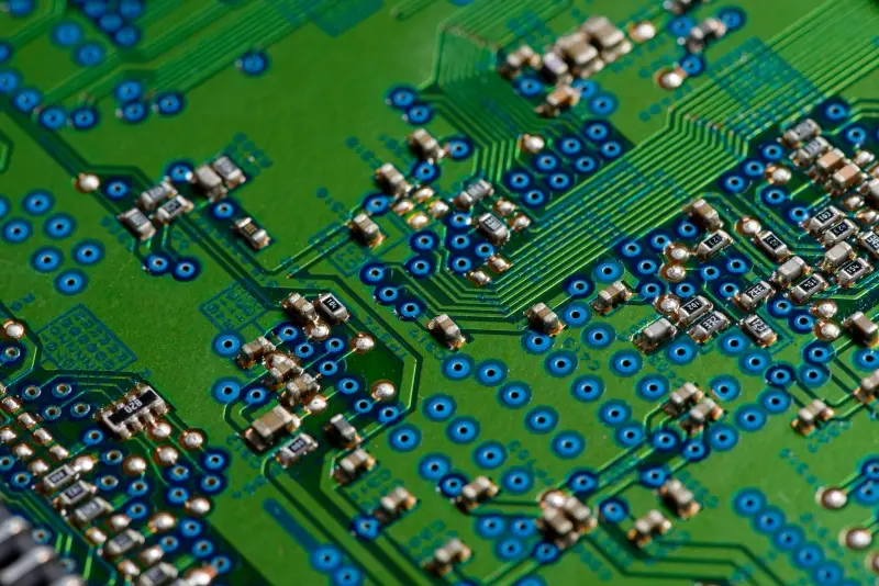
Copper has excellent thermal conductivity (~400 W/(m·K)) and is the most effective medium available on FR-4 to carry heat away from sources.
Use large, dedicated copper layers (power/ground planes) as heat spreaders. Leveraging FR-4’s relatively better in-plane conductivity (can reach ~0.6–0.8 W/(m·K) in some materials) helps disperse localized heat across a wider area, improving convection and radiation. Under moderate airflow or with effective heat-escape paths, large planes commonly reduce hotspot temperatures by several to over ten degrees Celsius; quantify with simulation and prototype thermal imaging.
Increasing copper thickness (2 oz, 3 oz, 4 oz) enhances both heat spreading and current capacity. Heavy copper reduces in-plane thermal resistance (degree depends on geometry and inter-layer coupling) but must be balanced against SI, controlled impedance, and cost. Heavy-copper PCBs are common in power electronics, industrial control, and EV applications. NextPCB supports professional heavy-copper fabrication for such high-power designs.
> Recommend reading: PCB Thermal Case Study: Copper Thickness for Uniform Heat Load
Thermal via arrays can lower component temperatures by several to over ten degrees Celsius in high-power surface-mount scenarios with good receiving planes; verify on prototypes.
Vias only perform when tied into an efficient receiving plane. Heat conducted vertically must be absorbed by a large, low-resistance copper area to spread laterally (X–Y). Heavy copper layers (e.g., 2–3 oz) often improve the synergy, subject to SI/DFM trade-offs.
When all FR-4-based optimizations (heavy copper, thermal vias, layout) are exhausted and requirements such as a temperature-rise limit of 20–30 °C are still unmet, higher-k substrates are the viable path.
> Recommend reading: HDI Via-in-Pad: Design, Fabrication, Reliability, and Performance
Specialty FR-4 with thermally conductive fillers or modified resins can raise k (e.g., 2.2 to 3.2 W/(m·K) in some products) while retaining FR-4 processing advantages. For environments requiring extreme structural stability (aerospace, automotive under-hood), high-Tg laminates (Tg ≥ 150 °C; NextPCB offers > 170 °C options) or polyimide systems minimize Z-axis expansion under high temperature and cycling, improving multilayer reliability.
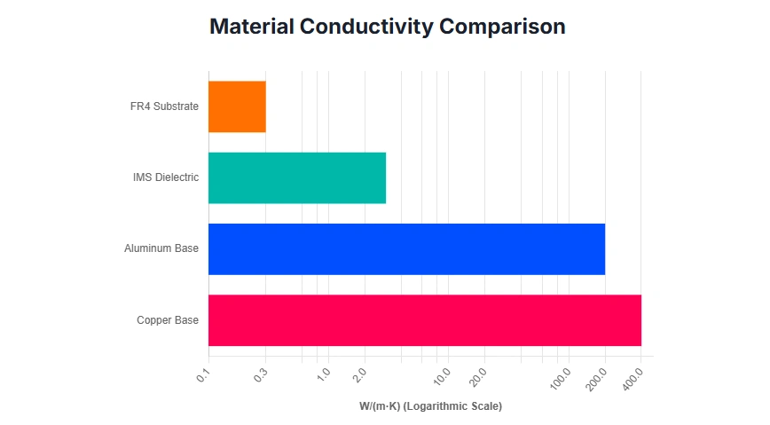
| Material Type | Typical Thermal Conductivity (k, W/(m·K)) | Primary Advantage | Typical Application |
|---|---|---|---|
| Standard FR-4 | 0.3 – 0.5 | Low cost; good electrical insulation | Low-power consumer electronics |
| Insulated Metal Substrate (IMS), Aluminum core | Metal core: Al ~150 – 200; dielectric: ~1 – 5 | Excellent structural heat dissipation; moderate cost | High-power LEDs, motor drives, power modules |
| NextPCB Copper Substrate | Copper base material ≈ 401 | Overall thermal path depends on dielectric and interfaces; in one reference structure/condition, example Rθ ≈ 0.2 °C/W (verify per design and boundary conditions) | AI servers, high-frequency circuits, extreme thermal demands |
| Ceramic / DBC (e.g., AlN) | ~150 – 240 | Very high thermal stability and reliability | Lasers, high-voltage power electronics, aerospace |
IMS note. An IMS typically consists of a thin, high-thermal-conductivity dielectric (commonly 1–5 W/(m·K)) sandwiched between a copper circuit layer and a thick Al or Cu substrate. The thick Al (~150–200 W/(m·K)) or Cu (~401 W/(m·K)) core provides heat-sink capacity, but the bottleneck is usually the dielectric layer and its thickness. The overall thermal path is the series/parallel combination of core, dielectric, copper foil, and interfaces. In practice, IMS can significantly reduce total thermal resistance (RθJA) vs. FR-4.
For the most demanding cases, PCB copper-substrate solutions use oxygen-free copper bases (~401 W/(m·K)) plus nano-ceramic coatings. The PCB’s equivalent thermal path is still governed by the dielectric layer and its thickness. In one AI-server GPU motherboard case, under a specified airflow and load, measured hotspot temperature dropped from 95 °C to 72 °C, enabling lower fan speeds and reduced noise.
Material selection is a trade-off between heat-removal capability and structural/thermal resilience. For very high power density (e.g., high-current switching, high-brightness LEDs), prioritize high-k substrates (IMS, copper). For continuous high-temperature environments with moderate power density (e.g., under-hood automotive, space electronics), prioritize long-term structural stability and thermal-cycling reliability (high-Tg FR-4 or polyimide).
Thermal planning should begin at the outset, not as a late-stage patch. NextPCB’s DFM analysis covers key thermal checkpoints: early hotspot prediction and temperature-rise estimation, spreading high-power components to avoid local peaks, and rigorous review of thermal-via arrays (density, plane connections, and whether filling is required). Proactive DFM reviews help identify and resolve long-term thermal risks, ensuring product stability.
In high-reliability sectors (medical, automotive), manufacturing quality and consistency underpin thermal performance. NextPCB’s quality system has achieved multiple international certifications. These attest process capability and consistency, providing a foundation for thermal reliability; final thermal performance still depends on sound design and verification.
FR-4 will remain a mainstay PCB substrate, but its low thermal conductivity demands advanced engineering approaches. Treat the FR-4 substrate as an active part of the thermal system, not merely mechanical support.
For projects targeting high performance and reliability—especially automotive, industrial, and high-power computing—plan thermal design from day one. Engage professional DFM thermal analysis early and partner with a manufacturer (such as NextPCB) that offers advanced materials and automotive-grade quality systems. As power densities rise, the industry will explore graphene, nanomaterials, and liquid-cooling systems. Mastering FR-4 and alternative-material thermal fundamentals remains the prerequisite for meeting tomorrow’s high-power challenges.
Engineering note: All improvements and temperature deltas cited are scenario-dependent (power density, stack-up, copper area, dielectric/interface properties, airflow and boundary conditions). Validate through 0D/1D estimates, 3D CFD (coarse-mesh), and EVT thermal measurements before freezing design.

Still, need help? Contact Us: support@nextpcb.com
Need a PCB or PCBA quote? Quote now


ginery
FR-4 (or FR4) is a NEMA grade designation for glass-reinforced epoxy laminate material.
andrei
Detailed FR4 Thermal Conductivity page, it's nice for engineers.