
 PCB Assembly
 Layer Buildup
 Online Tools
 PCB Design-Aid & Layout
 Mechanics
 SMD-Stencils
 Quality
 Drills & Throughplating
 Factory & Certificate
 PCB Assembly Factory Show
Certificate
PCB Assembly Factory Show
Certificate
Support Team
Feedback:
support@nextpcb.comRigid PCB was tracked early in the 20th century. Charles Ducas provided the very first patient for printed circuit boards. Between the 1960s and the 1970s, the rigid PCB was popular in the aerospace and defence industries, including guidance and radar systems. As technology advances, circuit designs have become even more complex and densely packed, and rigid PCBs have become more reliable and efficient.
This article provides a brief explanation of the rigid PCB including its manufacturing and design considerations.
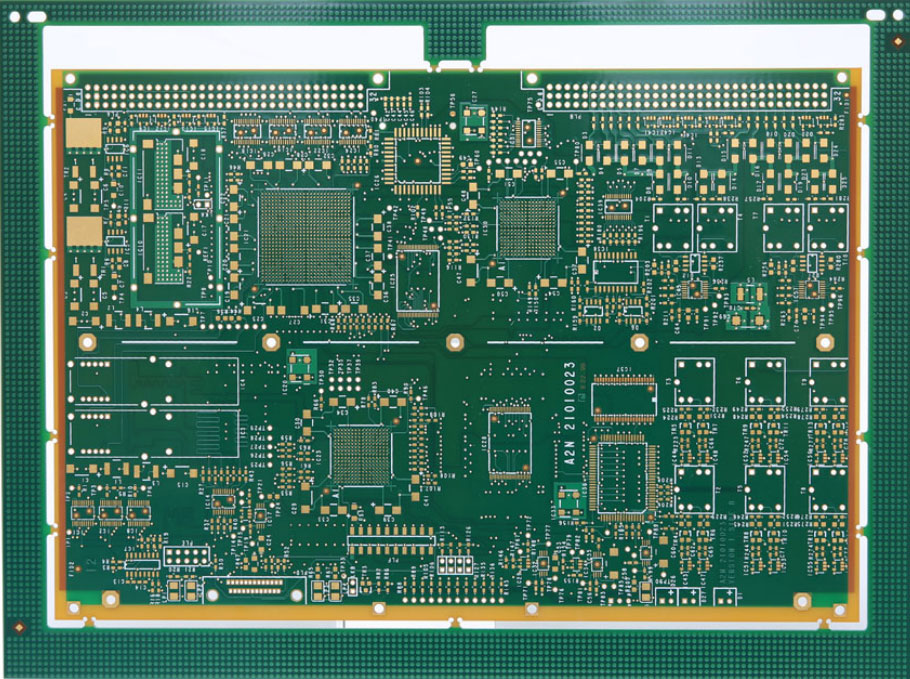
Rigid PCB is the regular PCB type, one of the world's largest manufactured PCB. Moreover, a rigid circuit Board is a non-flexible one that cannot be bent or forced out of shape. The rigid PCB can be of single-layered, double-layered, or multilayered PCB. Generally, this PCB comprises solid substrate materials that prevent circuit board distortions. In addition to this, it consists of the concrete substrate and the active and the passive components, which are soldered with automated through-hole soldering technology like automatic surface mount or wave soldering technology. Once the rigid PCB is finalized, it cannot be changed or modified.
Rigid PCB is generally used in GPS equipment, tablets, laptops, mobile phones, MRI systems, control instruments, etc.
The motherboard is one of the common rigid-type PCBs designed to distribute the power from the power supply.
Some of the basic characteristics of rigid PCB include:
The materials in the rigid PCB depend on the specification of the project. Below are the some of the basic design considerations:
However, the selection of the materials and the thickness depends on the specific applications of the PCB.
The basic manufacturing process of Rigid PCB includes:
It is the first step in any PCB manufacturing process. It includes the layout creation of the circuit, components placement, and trace routing on the PCB board.
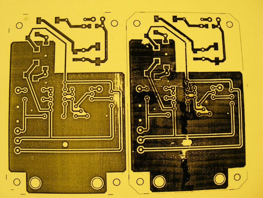
After the completion of the design, the next step is the photolithography process that transfers the circuit pattern into the PCB board. It involves using the photoresist on the PCB and exposing it to the light through a mask, thus developing the resistance for revealing the circuit pattern.
The next step after transferring the circuit pattern to the board is etching. Further, chemical etching creates circuit patterns on boards. An automated chemical etching machine and specialized handling equipment are used in this process.
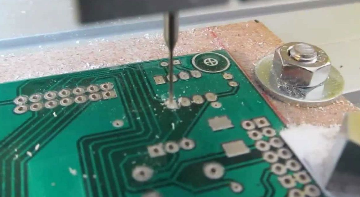
Drilling the holes for the circuit patterns is the next step after the etching process. The drilled holes should adhere to precise specifications, including size and shape. Two types of equipment usually perform this process. Drilling machines create holes in multiple boards. To get clean, precise holes quickly, they also use laser drills.
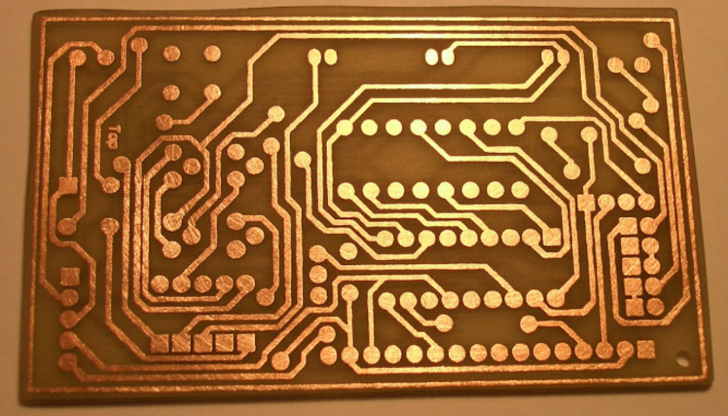
The copper plating process can begin with the completion of the drilling process. Applying copper to the circuit board creates the layer to layer interconnections. In this case, the manufacturers make use of automated copper plating systems.
Surface finish is applied to the PCB's surface. It can be HASL, ENIG (electroless nickel immersion gold), and OSP (organic solderability preservatives).
A solder mask on the PCB protects it from soldering on unwanted areas.
A silkscreen on the PCB provides identification information, such as part numbers and component placements.
Then the manufacturers inspect the PCB for any defects and tests to ensure that it functions properly.
Finally, it assembles the components in the PCB. Manufacturers insert the components into the hole and finally solder them.
These PCBs only have components on one side while another side is typically used for grounding. Then the components are soldered and placed on only one side of the board, entirely visible on the board. The conductive paths couldn't be intersected or overlapped as it consists of only one conductive layer. Because of the use of only one side of the board, it takes up a lot of space which is one of the drawbacks of this PCB. Due to this, the low-density requirements and basic and low-cost electronic devices like lighting boards, power supplies, timing circuits, etc, make use of this kind of PCB board.
It has the components on both sides of the board, with the metal plating running through holes connecting the two sides. Moreover, it combines the circuits on either side of the board using surface mount and through-hole technology.
Through-hole technology connects lead components to pads on opposite sides of a circuit board through predrilled holes. Besides, the electrical parts are precisely positioned on circuit boards using surface mount technology.
Test equipment, HVAC amplifiers, power monitoring system and UPS systems make use of the double-sided PCB.
It has multilayer of conductive materials with the components on both sides and additional layers between the interconnection. Further, it is designed in a sandwich fashion with various double-sided conductive layers divided by an equal number of insulating material sheets. Finally, these sheets are bonded and laminated at high temperatures and pressure to ensure that no air gaps and the final PCB assembly are properly stable.
Computers, mobile phones, tablets, GPS trackers, and many other complex circuits and devices use these types of PCBs.
These heavy cppper PCBs are designed to handle higher current loads; they use thicker copper traces than traditional PCBs.
These high Tg PCBs are made with a higher temperature rating. They can withstand higher temperatures during the soldering process.
High-frequency PCBs operate at higher frequencies, and they use materials such as Rogers, Teflon, and Arlon to improve its performance.
Metal core PCB has a metal core (usually aluminum or copper) that improves thermal conductivity, mostly in high-power-led lighting applications.
| Parameters | Rigid PCBs | Flex PCBs |
|---|---|---|
| Nature | Rigid and stiff type | Flexible and foldable type |
| Materials | Made up of FR-4; solid and inflexible materials | Made up of polyimide; flexible materials |
| Current Capacity of the wire | No need to provide the extra wire spacing | Should provide extra wire width or spacing |
| Manufacturing Process | Uses traditional method using solder mask | Requires extra overlay or coverlay to protect exposed circuitry |
| Design Complexity | Easier to design and manufacture | Complex to manufacture and required extra processes |
| Cost | Lower manufacturing cost | Expensive cost |
| Size | It is impossible to shrink the size | It is possible to shrink the size |
IPC has set many standards for the designs, manufacturing, and testing of both rigid and flexible PCBs:
For rigid PCBs, the most commonly used standards are IPC-6012 and IPC-6013.
IPC-6012, "Qualification and Performance Specification for Rigid Printed Boards," sets the requirements for designing, manufacturing, and testing rigid PCBs. It covers materials, dimensional tolerances, electrical testing, and environmental testing.
IPC-6013, "Specification for the Qualification and Performance of Permanent Bonded Copper-Clad Laminate and Adhesive Systems for Printed Boards," sets the materials, processes, and testing requirements of copper-clad laminates used in the manufacture of rigid PCBs.
For flexible PCBs, the most commonly used standards are IPC-2223 and IPC-2225.
IPC-2223, "Sectional Design Standard for Flexible Printed Boards," provides guidelines for designing and manufacturing flexible PCBs. It covers materials, dimensional tolerances, electrical testing, and environmental testing.
IPC-2225, "Design Guidelines for Flexible Printed Board Handed Assemblies", provides guidelines for manufacturing flexible PCBs.
The other types of IPC standards for rigid and flexible PCB include:
Generally, a rigid PCB is more cost-effective than a flex circuit. Thus, if your priority is the cost of the board, then you should go for the rigid PCB boards. Otherwise, you must check your requirements before selecting the desired PCB boards. In addition to this, you have to choose the right PCB manufacturer for your devices. Thus, NextPCB provides the solution for all types of PCB, including rigid, flex, and rigid-flex PCBs. We have global customers across the whole world. Get in touch with us to learn about our PCB capabilities and to get an instant PCB quote.
Rigid circuit boards provide lower design and development, including lower installation costs. Thus, many devices and instruments make use of the PCB and the circuit is in high demand and supply.
Still, need help? Contact Us: support@nextpcb.com
Need a PCB or PCBA quote? Quote now


 Printed Circuit Boards
 Surface

