Support Team
Feedback:
support@nextpcb.comSmart Irrigation System using ESP32
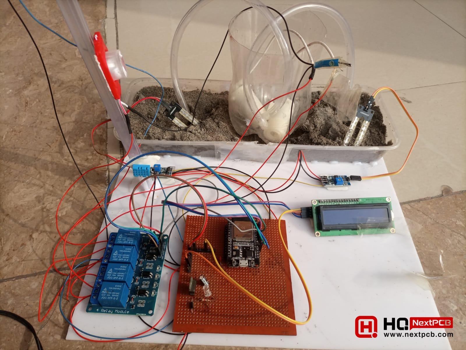
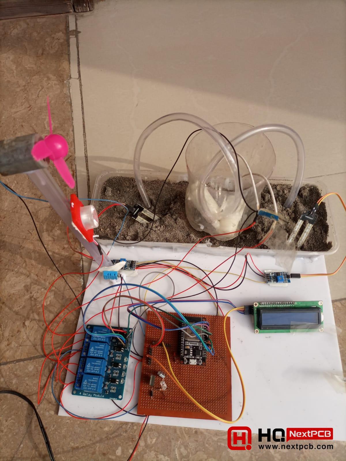
Hello learners! I hope you are doing great. Today, we are going to discuss one of the most basic and important projects in agriculture and soil domains using the Internet of Things (IoT). The smart irrigation system using ESP32 is a simple project that automatically takes care of the optimization of the basic soil conditions. The heart of this project is the ESP32, as it continuously checks for values from different sensors and sends commands to the other components to work accordingly.
The article provides a comprehensive walkthrough on how to design and code the project with ESP32 using the Arduino IDE, covering all necessary steps in detail. This project is done on a small amount of soil, but it can be enhanced on a large scale by increasing the number of components. In such cases, the basics of the project will remain the same, but things will be designed at a higher level. We’ll understand the scope of the project and study the basic workings and roles of each component in the project. The code and its explanation are given in simple words, and in the end, the details of the procedure are mentioned. Let’s start with the scope of the project to understand it well.
An irrigation system is an artificial application to water the soil on different levels using multiple systems such as tubes, sprays, or pumps. These systems fulfill the water needs of large agricultural areas where natural water is inadequate for the land. The scope of the irrigation project may vary from large projects of crop watering to small and simple watering systems for plants at home or offices. The project we are discussing is a smart irrigation system, so let’s discuss it in detail.
The Internet of Things (IoT) is a highly demanding field that is applied in multiple domains of life such as agricultural projects it can be used for the automation of multiple tasks. It is the most dominant field that has been revolutionized by integrating sensors, machines, data analytics, etc. It has the potential to increase efficiency and performance, improve resource management, enhance crop quality, and, as a result, empower farmers. The smart irrigation system is one such project that is extensively used in this field.
The smart irrigation system using ESP32 is a smart way to nurture the greenery at a small level with intelligence and efficiency. It is the best way to make sure that your plants are not overwatering or undervaluing but are at their best moisture level. Once this system is set to your place, there is no need to worry about watering your plants manually, and you can monitor the plant's health in terms of moisture and humidity.
In the technical world, efficiency and sustainability reign supreme, and the smart irrigation system using ESP32 has made the lives of both humans and plants easy. There are multiple advantages that highlight the importance of this project, and some of these are discussed below:
The wastage of water is one of the most serious issues worldwide, and smart irrigation systems are a small step against this wastage. The sensors of this system continuously sense the values of soil moisture and deliver water only when required. This is not only cost-effective but it also saves water. Moreover, the excessive water given to the plant is harmful to its health.
The water schedule does not remain the same all the time, but multiple factors affect the required amount of water for the plant, such as humidity in the air and temperature. These factors are regularly monitored by the sensors, and the display screen shows the values as well. As a result, the plant gets the water exactly according to its needs.
The frequency of watering is an important factor in the plant's health and yield. With the help of this system, the optimal watering level leads to thriving plants with healthy growth. The regular and appropriate amount also helps the plant fight issues related to improper watering, such as fungal growth, water-loving pests, etc. In short, a healthy plant has fewer chances of attack and provides more yield.
The most prominent advantage of this watering system is that it saves time. This system can be controlled remotely via a smartphone; therefore, the owner does not have to go to a particular place in the home to water their plants. This can be done from any corner of the house, or even if the owner is outside the house, he or she can have a look at their plant health and other parameters.
The plants have a unique nourishment system that requires watering early in the morning or at the optimal time. This is usually different from the human routine, and the automatic watering system is a stress-free solution in such situations.
The ESP32 is a microcontroller, and it is one of the most extensively used computers in IoT projects. In the smart irrigation system, the ESP32 acts as the heart, controlling the flow of information from the sensor to the output devices and also initiating action according to the required conditions.
The plus point of this microcontroller is that it is easy to install and can be coded on the lightweight Arduino IDE. It is the central point of the system that takes the information from the sensors, connects the components with the internet, and controls the actuators.
In simple words, the ESP32 is the middle point where all the components are connected. It is coded in such a way that it takes the values from the sensors and shows them on the LCD and dashboard of the website. Once any value reaches the threshold value, it sends the signals to the respective device to optimize the required parameter.
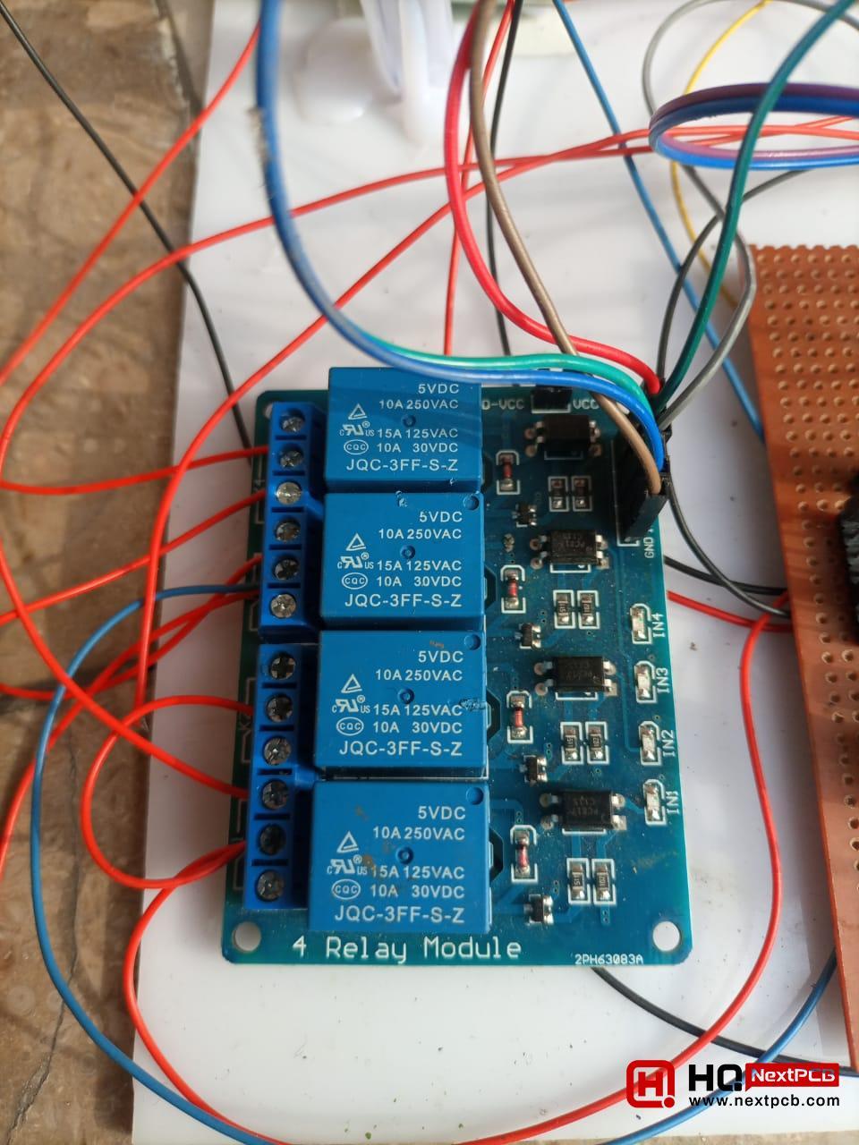
The water flow in the smart irrigation system using ESP32 is controlled with the help of relays. It has multiple duties, such as:
Free Components Worldwide Shipping
The moisture sensor reads the volumetric water content in the soil. The main domains where this sensor has scope are given next:
The moisture sensors do not calculate the amount of water content directly; instead, these sensors measure the soil properties related to the water content in a predictable way. You will encounter multiple types of moisture sensors, such as Capacitance Sensors, Time Domain Reflectometry (TDR) Sensors, Neutron Attenuation Sensors, Tensiometers, etc.
Here, I would like to gain an understanding of the fundamental principles of the moisture sensor employed in this project. This moisture sensor consists of two parts:
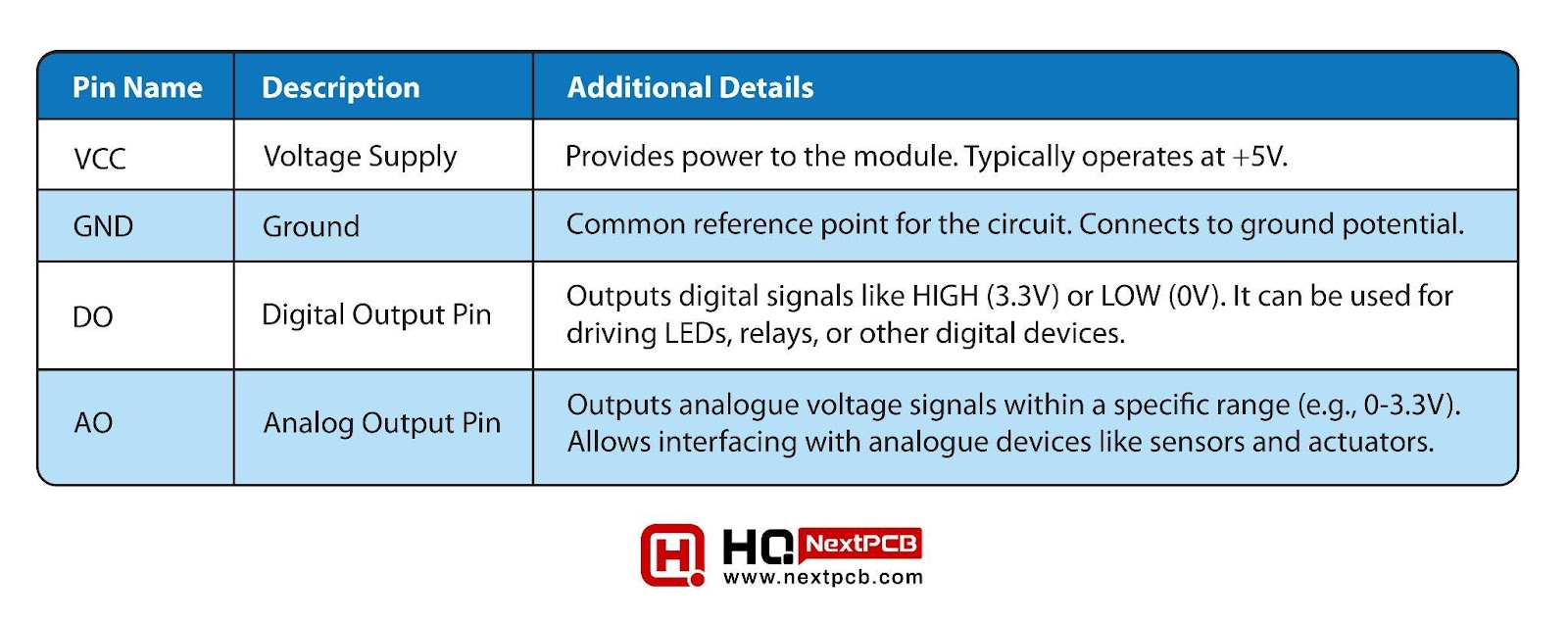
The basic properties of the soil moisture module that will help you understand their functionality in the project are mentioned here:
|
|
|
|
|
|
|
|
|
|
|
|
|
|
|
|
|
|
|
|
Now, let’s understand the features of the capacitive plates attached to this module:
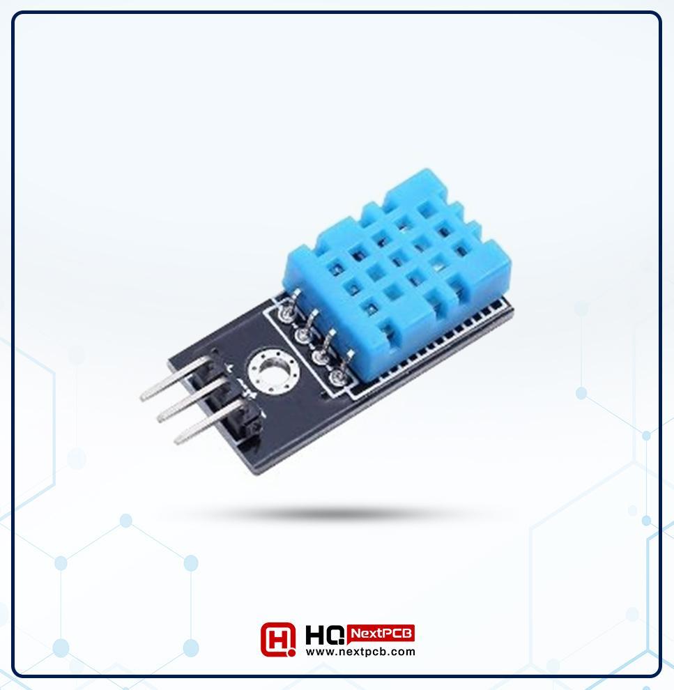
The DHT11 is a temperature and humidity sensor that has a wide range of applications in similar fields, as discussed before in the moisture sensor. To provide the required calculations, it has two types of sensors in it:
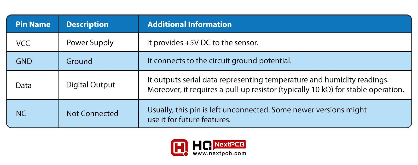
As a result, it provides the digital reading on its digital output pin. This sensor has four pins and the name and description of each of it is given here:
|
|
|
|
|
|
|
|
|
|
|
|
|
|
|
|
|
|
|
|
The plus point of using this instrument in our project is, that it provides the values of humidity and temperature at the same output pin so that it makes the project more simplified.
In this project, this sensor is controlled with ESP32 coding. Here, the triggered values are set through the code and as a result, the ESP32 is able to turn the fans ON/OFF according to the values sensed by the DHT11.
A small fan is attached to the ESP32 that is turned on only when the temperature of the system rises to a particular value. These values are programmed in the ESP32 code.
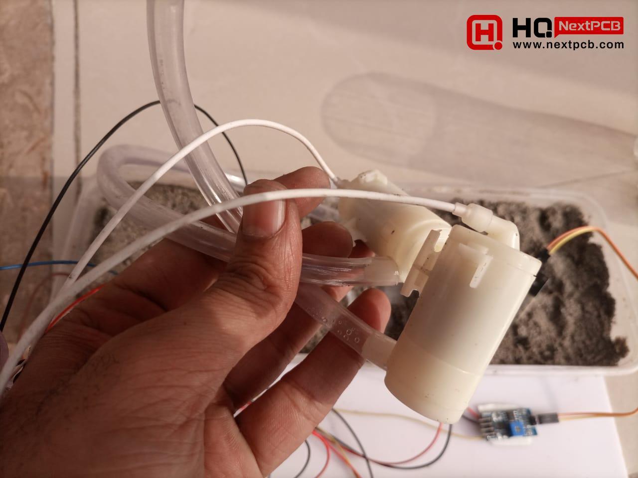
The compact-sized pumps are used in the system that is used to get the water from the resource and supply it to the field. These get the signals from the ESP32 that turn the pump only when required.
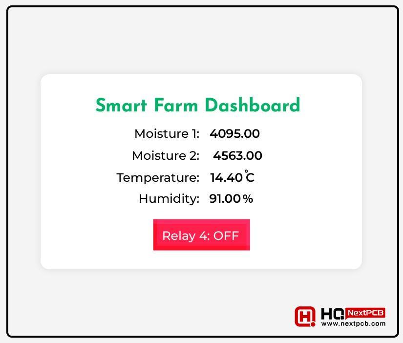
The information on the smart irrigation system is seen on the smart device's web browser. This information is obtained from the ESP32 and can be controlled and monitored continuously. The information on the dashboard includes the following four factors:
The details of each of them are discussed below:
The irrigation system consists of two moisture sensors labelled sensor 1 and sensor 2, and the values obtained are numbered according to their respective sensors. Collectively, both provide information from the different areas of the soil. The values of these sensors depend on different environmental factors, such as:
The values of the humidity in the system are continuously sensed by the DHT11 sensor, and the values from the output pins are fed into the ESP32. This enables the user to see humidity values through the dashboard.
Similar to the humidity values, the temperature is obtained from the output pin of DHT11. These calculations are fed into the ESP32, and as a result, the temperature of the smart irrigation system can be examined through the dashboard.
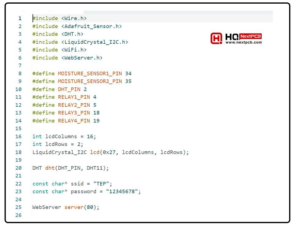
#include
#include
#include
#include
#include
#include
#define MOISTURE_SENSOR1_PIN 34
#define MOISTURE_SENSOR2_PIN 35
#define DHT_PIN 2
#define RELAY1_PIN 4
#define RELAY2_PIN 5
#define RELAY3_PIN 18
#define RELAY4_PIN 19
int lcdColumns = 16;
int lcdRows = 2;
LiquidCrystal_I2C lcd(0x27, lcdColumns, lcdRows);
DHT dht(DHT_PIN, DHT11);
const char* ssid = "TP";
const char* password = "12345678";
WebServer server(80);
void setup() {
Serial.begin(115200);
pinMode(MOISTURE_SENSOR1_PIN, INPUT);
pinMode(MOISTURE_SENSOR2_PIN, INPUT);
pinMode(RELAY1_PIN, OUTPUT);
pinMode(RELAY2_PIN, OUTPUT);
pinMode(RELAY3_PIN, OUTPUT);
pinMode(RELAY4_PIN, OUTPUT);
lcd.init();
lcd.backlight();
lcd.setCursor(0, 0);
lcd.print("Smart Farm");
dht.begin();
WiFi.begin(ssid, password);
while (WiFi.status() != WL_CONNECTED) {
delay(500);
Serial.print(".");
}
Serial.println("WiFi connected");
Serial.print("IP Address: ");
Serial.println(WiFi.localIP());
server.on("/", HTTP_GET, handleRoot);
server.on("/relay4/on", HTTP_GET, handleRelay4On);
server.on("/relay4/off", HTTP_GET, handleRelay4Off);
server.begin();
}
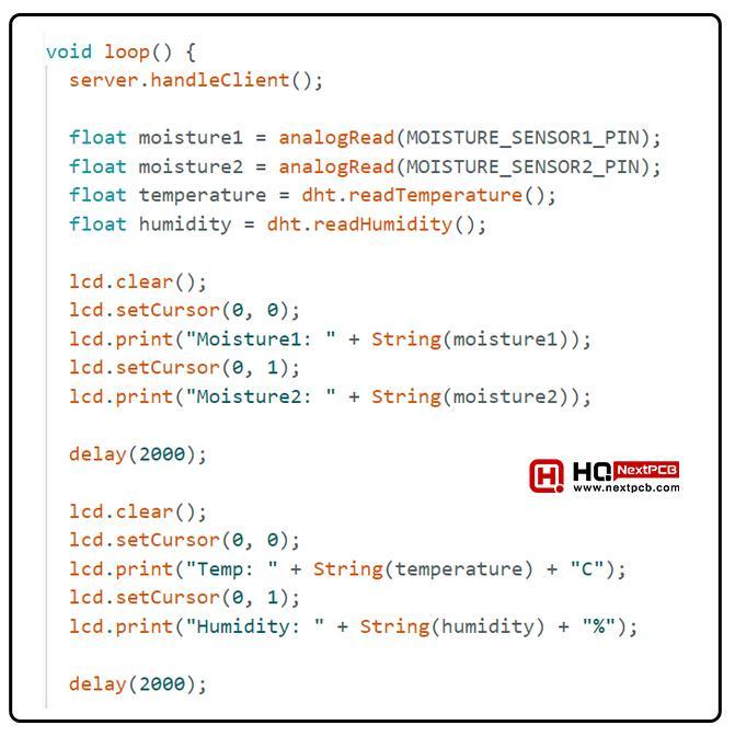
void loop() {
server.handleClient();
float moisture1 = analogRead(MOISTURE_SENSOR1_PIN);
float moisture2 = analogRead(MOISTURE_SENSOR2_PIN);
float temperature = dht.readTemperature();
float humidity = dht.readHumidity();
lcd.clear();
lcd.setCursor(0, 0);
lcd.print("Moisture1: " + String(moisture1));
lcd.setCursor(0, 1);
lcd.print("Moisture2: " + String(moisture2));
delay(2000);
lcd.clear();
lcd.setCursor(0, 0);
lcd.print("Temp: " + String(temperature) + "C");
lcd.setCursor(0, 1);
lcd.print("Humidity: " + String(humidity) + "%");
delay(2000);
Serial.print(moisture1);
Serial.print("\t\t");
Serial.print(moisture2);
Serial.print("\t\t");
Serial.print(temperature);
Serial.print("\t\t");
Serial.println(humidity);
// Auto-control relays based on sensor readings
if (moisture1 <= 3000) {
digitalWrite(RELAY1_PIN, HIGH);
} else {
digitalWrite(RELAY1_PIN, LOW);
}
if (moisture2 <= 3000) {
digitalWrite(RELAY2_PIN, HIGH);
} else {
digitalWrite(RELAY2_PIN, LOW);
}
if (temperature <= 22.0) {
digitalWrite(RELAY3_PIN, HIGH);
} else {
digitalWrite(RELAY3_PIN, LOW);
}
}
void handleRoot() {
float temperature = dht.readTemperature();
float humidity = dht.readHumidity();
String html = "";
html += "
html += "";
html += "Smart Farm Dashboard";
html += "Moisture 1: " + String(analogRead(MOISTURE_SENSOR1_PIN)) + "";
html += "Moisture 2: " + String(analogRead(MOISTURE_SENSOR2_PIN)) + "";
html += "Temperature: " + String(temperature) + " °C";
html += "Humidity: " + String(humidity) + " %";
// Relay 4 control button
html += "
html += digitalRead(RELAY4_PIN) == HIGH ? "on" : "off";
html += "" id="relay4Button" onclick="toggleRelay()">Relay 4: ";
html += digitalRead(RELAY4_PIN) == HIGH ? "on" : "off";
html += "" id="relay4Button" onclick="toggleRelay()">
html += digitalRead(RELAY4_PIN) == HIGH ? "on" : "off";
html += "" id="relay4Button" onclick="toggleRelay()"> html += digitalRead(RELAY4_PIN) == HIGH ? "ON" : "OFF";
html += "";
html += "";
html += "";
html += "";
server.send(200, "text/html", html);
}
// ... [previous code remains the same]
void handleRelay4On() {
digitalWrite(RELAY4_PIN, LOW); // Turn on Relay 4
server.send(200, "text/plain", "Relay 4 turned ON");
}
void handleRelay4Off() {
digitalWrite(RELAY4_PIN, HIGH); // Turn off Relay 4
server.send(200, "text/plain", "Relay 4 turned OFF");
}
// ... [rest of the code remains the same]
If, at the moment, you are unable to understand the code, then let me divide it into different parts and explain them one by one.
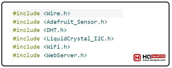
The first step is to include all the libraries that will help us avoid long codes because these have pre-defined codes and the user does not have to repeat the lines. In this code, these libraries handle features of wifi connection with the ESP32, LED display, connection with the web server, read the values from the DHT11 sensor, and include the values of the sensors in the code.
The next step is to define the pins of the ESP32 with respect to the physical connection used in the project. It is important to define the right pins because these will be used throughout the codes. The simple #define function is used for this purpose, and the user can have any name for the pin. Usually, user-friendly names are considered.
The LCD library included in the code will help us set up the real-time LCD in the project. In these lines, the numbers of rows and columns are defined and are used in the pre-defined function in the library. It is because the LCDs come in different versions in which the size and specifications vary. Through this part of the code, the ESP32 is understood to show the output that perfectly aligns on the screen.
Similarly, the DHT library is used, and we define the pin in its pre-defined function. In the same part, the password and name of the WiFi are specified. The right data type for this information is “character.” When the compiler knows the basic settings, the server is ready to run; therefore, we are using the line of code to run the server at port 80.
This is the part of the code that will run only once. When the compiler reaches these lines, the output on the project starts showing. The defined pins are used here, and there are two possibilities for these pins, that is, they are either input or output. The state of the pins has been mentioned here according to their functions.
This is the point where the label of our project, that is, “Smart irrigation system,” is shown on the screen. The DHT11 sensor starts its work, and the server starts and checks if the right credentials are provided by the users. The WiFi library starts its work, and the server is set so that the user may see the information.
The void loop is the one that will run continuously; therefore, here, we are using the values that have to be checked all the time when the project is running. In simple words, the basic motto of this project is to examine the humidity, moisture, and temperature without any break; therefore, we are using such settings in this portion of the code.
With this part of the code, the LED continuously takes the values from the ESP32 and shows the analog values on it.
In every step, the ESP32 refreshes the LCD through the setCursor() function, and every time, it shows the required readings of moisture 1, moisture 2, humidity, and temperature. The threshold values are set here through an if-else loop so that the pins work according to the values sensed by the sensors.
This is the part of the code that handles the interface of the webpage. Here, the settings of the colour scheme, fonts, style, and string are present. This is the HTML code that sets the body and head of the webpage. A button is designed here for the relay 4 and the user can turn it ON/OFF according to the requirement.
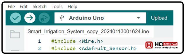
Now, that you know all the basic information about the smart irrigation system, it is easy for you to create one by yourself. Simply follow the given steps:
Free Components Worldwide Shipping
This project has multiple advantages, but right now, it does not provide the perfect performance. The following are some important limitations in this regard:
Hence, today we have created the smart irrigation system using ESP32. This system can be incorporated in houses and offices, and if made at a higher level, can be used in the fields and crops as well. This was just a small idea to present you with the working of different components. We have understood the scope of this project and started learning its production step by step. I hope your project is working fine as mine but if you are stuck at any point, you can contact us.
- ESP32 BLE(Bluetooth Low Energy) Control in Arduino IDE
- Free Worldwide Shipping on Over 600,000 Electronics Components with HQ Online
- Free PCB Assembly Offer is Now Live: Experience Reliable PCB Assembly from HQ NextPCB
- HQ NextPCB Introduces New PCB Gerber Viewer: HQDFM Online Lite Edition
Still, need help? Contact Us: support@nextpcb.com
Need a PCB or PCBA quote? Quote now
|
Dimensions: (mm) |
|
|
Quantity: (pcs) |
|
|
Layers: |
Thickness: |
|
|
|