Introduction
A multimeter is the main component of electronic engineering used to measure different parameters of electrical-based values. There are different symbols mentioned on the meter that are employed to define the values of different parameters. There are a larger number of symbols that make it difficult for any new electronic lover or student to learn their operation and uses. Here we will explain each symbol in detail and its related function. So let's get started!
What Is a Multimeter?
The short form of the multimeter is a multiple-meter, electronic device that is used to measure different parameters of current. It is used to measure different features of any circuits and devices. it measured current in amperes, voltage in volts, and resistance in ohm meter. There are four main parts of this meter. The first one is the display screen that shows the calculated values, and buttons used to on and off it. it has a rotary dial that is used to vary the measuring unit. It has two leads that are used for testing connections in circuits.
Multimeter Parts
Different parts of the meter are used to find values of different electrical parameters. Those are listed here
- Display:
- Analog Display: In the analog meter display the moveable needle gives the measured value on the scale.
- Digital Display: In a digital multimeter, the measured value is shown in the form of numbers. it comes with some digits and symbols (used for units) that show the values measured and their unit.
- Selection Dial (Function/Range Selector)
- it is used to select the meter's required measured function or unit like current, voltage, resistance, and value range. Selecting an accurate range is important to measure value correctly.
- Function Buttons
- In some digital meters, there are some extra buttons such as HOLD used for reading holding, choosing a certain range, or for on the backlight button
- Auto-ranging Switch
- In the auto range meter, the device selects an accurate range for measuring the value. It minimizes the use of manual range selection.
- Battery Compartment:
- The power is given to the meter through batteries, and the compartment of the battery is used to replace the battery if needed.
- Input Jacks:
- Common or (COM): It is a common terminal that is used to work as the reference point for any measured value or parameters.
- Volts/Ohms/Amps (VΩA): These input jacks are used to measure the voltage, resistance, and current values. Before finding the required value first select jack according to the functions then probe leads are connected in jacks.
- Probes:
- These probes are attached with input jacks and used for electrical connection with the required circuit. These probes are red and black colored, red is positive, and black is negative leads.
- Fuse :
- There is a fuse connected in current paths to measure the current without affecting the meter from a high current value
Get Instant Online Quote
Basic Multimeter Symbols and Their Meanings:
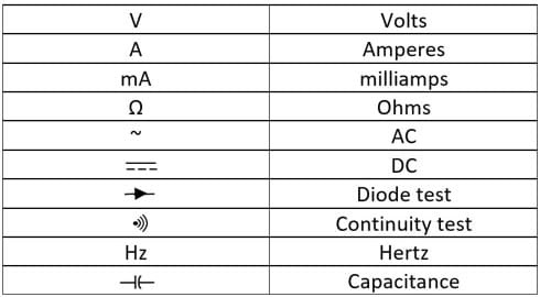
- DC Voltage (V): It measured the DC volts and denoted with the capital letter V, three hyphens, and a straight line on top. For measuring the voltage move your dial to this symbol and the DC voltage of your circuit will shown on the display
- AC Voltage (mV~): It is used to measure the AC voltage. It is denoted with mV having 3 hyphens and a straight line on top. It is used to measure the voltage of AC signal with low value, especially in small-size circuits.
- Resistance (Ohm): It is used to measure the resistance of circuit components in ohms. It is denoted with Ω(omega). just move the dial to this symbol of resistance to measure the resistance of the component. It is also used to check whether the fuse is interacting or not
- DC Current (Ampere) (I): it measures DC. It is denoted with V having three hyphens and a straight line at the top. For measuring the DC of the circuit set the needle on this symbol.
- Diode Test: This is used to test the diode of the circuit. it exits with the continuity symbol and has an arrow symbol with a plus sign. To use this symbol, just set the needle to this symbol and click the function button. Using this symbol we can find whether the diode is working or not.
- Current Gain (hFE): It is used to find the current gain of a transistor connected in the circuit.
- OFF: it used to off the multimeter.
- Hold: it is used to freeze the display and hold the current measured reading on the screen for some time.
- Continuity Test: It is used to check the current between two points. Denoted with a sound wave symbol, it measured the continuity between two points. So we can find using this function that the circuit is open or short. it is an important function to find different faults in the circuit.
- Brightness Button
- it is used for adjusting the screen brightness. it is the best option for meter use in outdoor uses and with a dim screen, it helps to see reading
Advanced Multimeter Symbols and Their Meanings
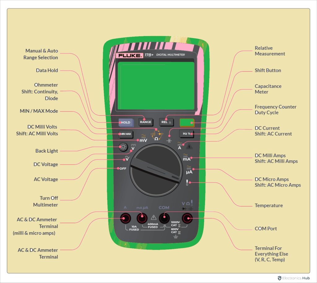
- AC Current: This symbolic representation shows the features of a meter to measure AC current.
- Temperature Symbol: it is used to measure system temperature. It needed a temperature probe to measure temperature.
- Capacitance Symbol: This is used to measure the features of the meter to find the value of capacitance in Farad. It is used to find the capacitor capacitance which means how much charge capacitance can store
- Hz Symbol: This symbolic representation is used to measure frequency hertz. it finds the value of frequent signal of electrical signals.
- Duty Cycle: it denotes duty cycle features of meters. The ratio duration of the signal's high value with the total time of the signal is called the duty cycle
What Are The Units Of Multimeter?
Students and new learners of electronics who work for the first time on a multimeter will face difficulty in using this meter. We cannot see resistance, voltage and current mentioned on the meter since these parameters are mentioned in their respective units, like V for resistance, Ω for ohm, and A for current. These units also come with sub-units that are K used for kilo means 1000 times.
M used for Mega or Million means 10,00,000 times.m is milli for 1/1000 and µ is micro means 1/million
What does 200m mean on a multimeter?
If there is 200m written on the meter it is a measuring the range of the meter. Here 200m is for milliunits. m is used for milli which means 1/1000. If we have to measure current, voltage, and resistance on the meter and 200m is set on the meter it means the highest value a meter can measure is 200 milliunits.
Here we can see some other measuring ranges.
- 200mV is used for measuring the highest 0.2 volts
- 200mA is used to measure 0.2 ampers highest value or range
- 200Ω range measures 200-ohm resistance.
What is the symbol for DC volts?
The symbol of DC volts is V having a straight line on it. It is used to denote V with a continuous horizontal line over it. it means that the meter is set to measure voltage in DC value.
Multimeter Safety Measures
- Meter Inspection
- Before using the meter check that the meter is not damaged from any part like not having a cracked display, open wires, or broken probes. If you find any damage, do not use the meter.
- Accurate Setting of meter
- also ensures that the meter has an accurate function and range for measuring value. if an incorrect setting is made will not get accurate values
- Power Off:
- When you are connecting leads or varying settings OFF the power of circuits or devices that going to test. It reduces the chances of electric shock and prevents the meter from being damaged
- Must have Hands Dry:
- Try to avoid working with electrical components or meters with wet hands. Moistures can cause electric shock.
- Circuit Isolation
- Before finding the value of a circuit or any device try to isolate it. It saves that circuit to make a connection with neighboring devices
- Safety Ratings:
- For Current and volts check the safety ratings of the meter. Make sure the meter is rated for current and voltage before measuring these values
- Check the fuse
- if the meter has a fuse, make sure it is in good condition and set at an accurate rating. Replace the burnt fuse with the correct one
- Probe Safety:
- Check probes to find any damage. Make sure the insulation is properly configured. Use the probe to have safety parameters
- One Hand Rule:
- Try to follow the hand rule by putting one hand in your pocket or behind your back. It prevents current from flowing from your chest
Get Instant Online Quote
Difference between a voltmeter and a Multimeter
|
Feature
|
Voltmeter
|
Multimeter
|
|
Measurement Type
|
It just measures the value of the voltage
|
It can measure resistance, current, and voltage
|
|
Purpose
|
it is made for measuring the voltage.
|
It measures different parameters of the electrical circuit
|
|
Components
|
It normally comes with a voltage-measuring circuit
|
voltage, current, and resistance measurement
|
|
Function
|
it finds the value of the difference of potential between two points
|
Measures current flow, voltage, and resistance in a circuit
|
|
Display
|
it comes with a digital display for volts.
|
it has an analog or digital display for showing different readings
|
|
|
|
|
|
Settings
|
it is set for measuring different ranges of voltage
|
it set to find different parameters
|
|
Applications
|
Used for electrical testing and troubleshooting purposes
|
its main applications are electronics, electrical, and automotive
|
|
Cost
|
Due to certain functions, its cost is low
|
it is costly due to the different functions
|
The difference between an Ammeter and a Voltmeter
|
Feature
|
Ammeter
|
Voltmeter
|
|
Function
|
It is used to measure the current in the circuit
|
It measures potential differences across two points of the circuit
|
|
Placement in Circuit
|
it connected in a series configuration in the circuit
|
it is used to measure voltage in the parallel configuration of the circuit
|
|
Internal Resistance
|
it has less inner resistance to have low voltage losses
|
it has high resistance to avoid current flow
|
|
Reading
|
it shows currently in ampers
|
it shows the current in volts V
|
|
Use Case
|
It measures current at a certain point of the circuit.
|
it measured across the required points of the circuit
|
|
Effect on Circuit
|
it has less resistance in the circuit
|
it affects voltage due to high inner resistance
|
|
Safety Precautions
|
The rating of the current must match the current rating of the circuit
|
Must select voltage rating to avoid damage or any overloading
|
|
Symbol
|
Its symbol on the meter dial is A or Am
|
it is denoted with V or volts on a meter
|
|
Connection Type
|
It connects in series combination with the circuit
|
parallel to the load or circuit.
|
|
Measurement Range
|
It measured current in different values with unit ampere.
|
It measured different values of voltage in volt unit
|
How to do a Diode Check on a Multimeter
The diode check function of the meter is very beneficial for measuring the current direction. The exact working of the diode check of the meter helps to be used for different functions and in some multimeters it does not exist.
What is the Difference between a multimeter and a clamp meter?
A multimeter and clamp meter both are used to measure different electrical parameters. A clamp meter measures the value of current without affecting the circuit so it is the best option to use in closed spaces or measure the current of a live wire.
While multimeter is connected to a circuit to find the value of current, voltage, and resistance, and its accuracy is higher than a clamp meter
Conclusion
The knowledge of different symbols of the multimeter is important to work on the electrical power system and any circuit. It helps to find accurate values of different parameters and save the meter to avoid any damage during the test. Whether you are a new electronic learner or an expert engineer, you must have an understanding of the different symbols of the multimeter to use to properly find the different parameters of the circuit like resistance, current amperes, etc. It also helps to find any fault of a circuit like a short circuit or open circuit.
You may also be interested in...
- Capacitor Symbols: A Guide to Understanding the Different Types
- How To Read Electrical Schematics
- Free PCB Assembly Offer is Now Live: Experience Reliable PCB Assembly from HQ NextPCB
- HQ NextPCB Introduces New PCB Gerber Viewer: HQDFM Online Lite Edition


