
Support Team
Feedback:
support@nextpcb.comThe key is the most common input device in a single-chip microcomputer (SCM) system. In this article, we will introduce some hardware and software design skills of keys. There are usually four schemes for the key design.
Scheme 1. The GPIO port directly detects a single key, shown in Figure 1.1.
Scheme 2. The matrix key is used for the situation of more keys, shown in Figure 1.2.
Scheme 3. Connect the key to the external interrupt pin and use the edge signal generated by pressing the key to detecting the keyboard, shown in Figure 1.3.
Scheme 4. Using SCM ADC to recognize the keys. The voltages on the ADC interfaces can be different after different keys are pressed. Then the keys can be recognized according to the different voltages, shown in Figure 1.4.
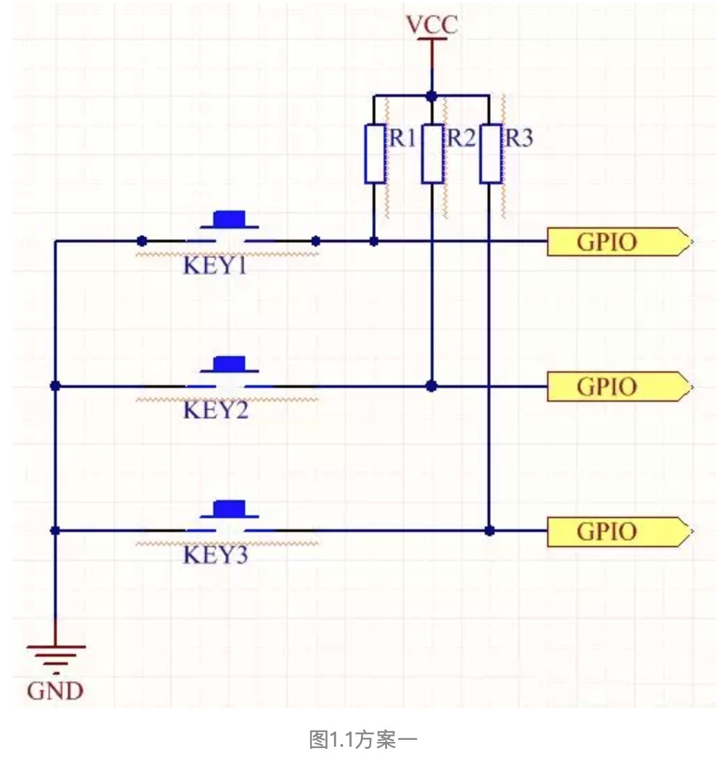
Figure 1.1 Scheme 1
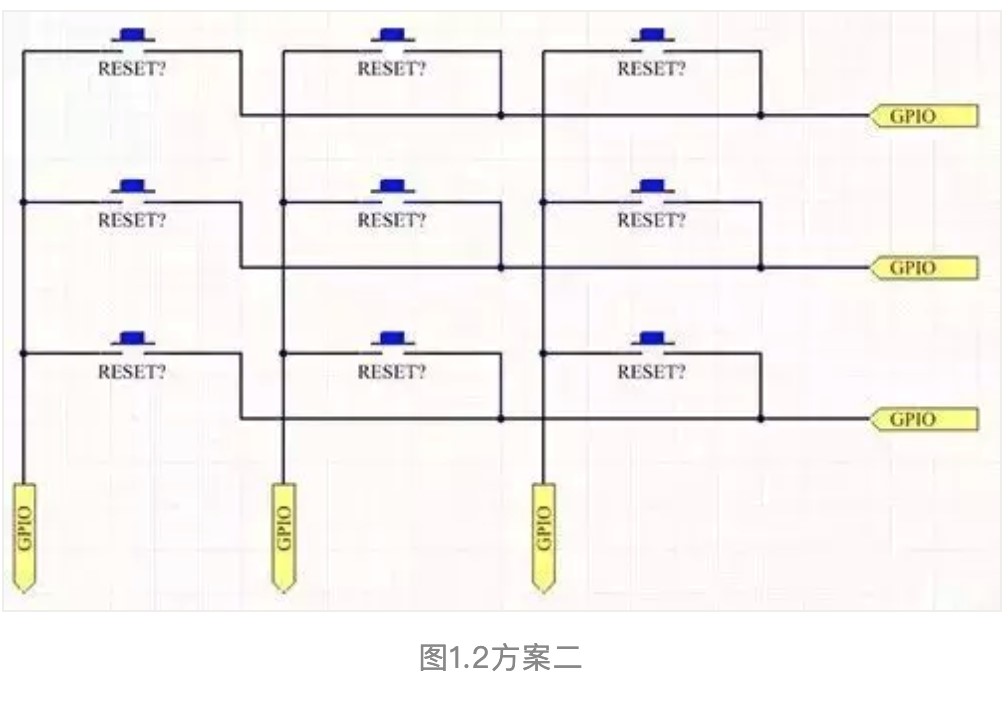
Figure 1.2 Scheme 2
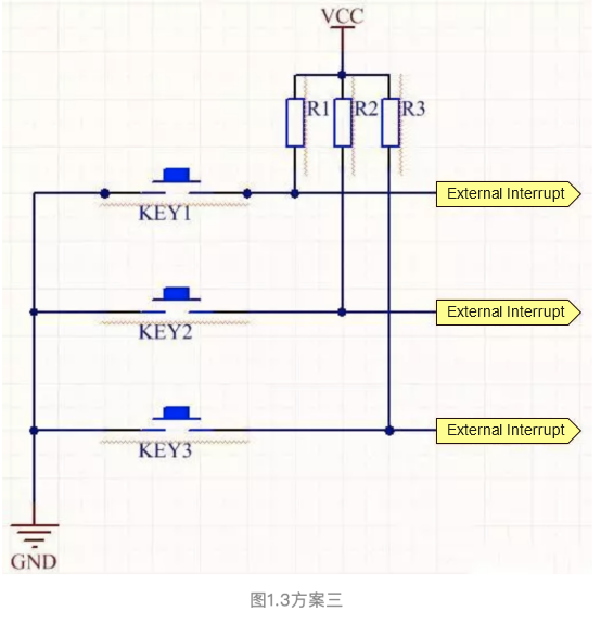
Figure 1.3 Scheme 3
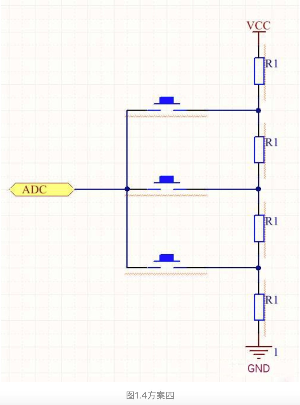
Figure 1.4 Scheme 4
The advantages and disadvantages of the above four schemes
Scheme 1. The first one is the simplest and most basic scheme, which is easy to understand and use for beginners of the single-chip microcomputer. But the problem is that you need to constantly check whether the key is pressed in the main loop, and you need to do anti-jitter processing. And if one function task in the main loop takes a long time, the keys will have different degrees of failures.
Scheme 2. The benefit is that this scheme can extend as many keys as possible in limited DPIO situations. The disadvantage is the same as the first scheme that you need to constantly check whether the key is pressed in the main loop.
Scheme 3. This scheme is the most efficient and does not need to detect whether the key is pressed or not. But the microcontroller is required to have sufficient external interrupt interface for use.
Scheme 4. The advantage is that multiple keys can be identified only using one single-chip ADC interface and one wire. The disadvantage is that the key may be confused once the internal contact of the key is bad. And the jitter produced by pressing the key will cause specific recognition errors.
I will share the key design solutions summarized from my study and work based on the above four common designs of the keys.
Improvement 1. Add a circuit on the basis of scheme 1, making the interrupt produces when any keys are pressed, and then recognize which key is pressed in the interruption. This solution will significantly improve efficiency because no circular scanning is required. The improvement scheme is shown in Figure 1.5. We only need to add a diode for each key and utilize its wire and characteristics to achieve signal interruption by pressing any keys, and the keys do not affect each other. From my actual tests, the ordinary rectifier diode does work.
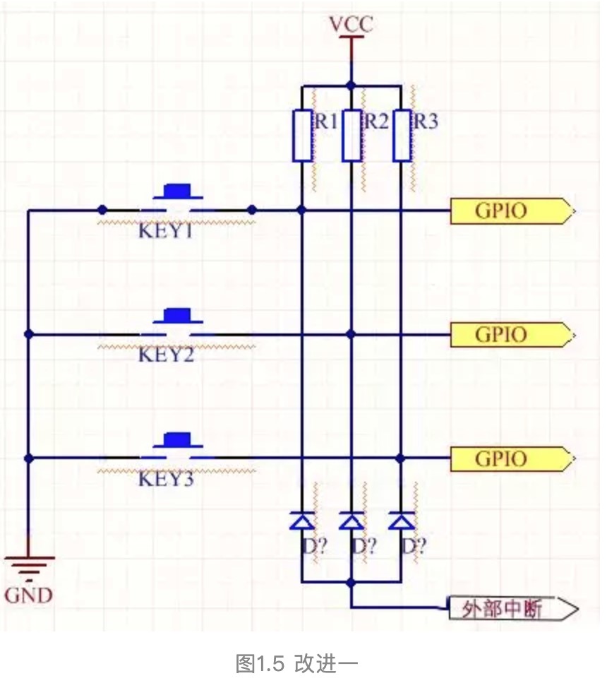
Figure 1.5 Improvement 1
Improvement 2. Based on the original ADC keys, a diode can also be added to realize the key interruption and carry out AD conversion in the interrupt service program to identify the keys. The circuit is shown in Figure 1.6.
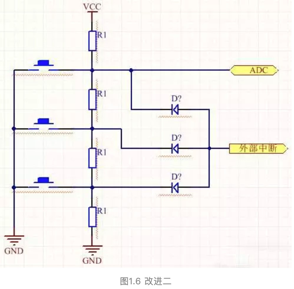
Figure 1.6 Improvement 2
Improvement 3. The key inevitably will produce jitter so that the key jitter can be eliminated through hardware and software. Now I will share a straightforward and effective method of hardware jitter elimination: parallel a capacitor of model 104 or so to a key, then jitter can be avoided, and the software doesn’t need to do anything.
Improvement 4. In the scheme of key scan detection, if one of the functions in the main loop takes a long time, the key will be failed for a long or short duration. Now I will share a solution to solve this problem. Put the key scan into timer interrupt, so that you can detect the press situation of the keys periodically without being affected by the main loop.
Besides, this solution can analyze the different states of the key, such as these four states: press, be pressing, bounce, no pressed, and to achieve richer functions.
However, there needs to note two points: the first is that the timing of the timer cannot be too long or too short. It is not easy to detect whether a key is pressed if the time is too long, and if the time is too short, it will take up a lot of time resources. The second is that the interrupt service program needs to be simple and clear, only used for detection. The key response needs to be completed in the main loop through the global variables. And try not to occupy too much time in the interrupt service function.
Disclaimer: The content of the article is the author’s personal view and does not represent the position of NEXTPCB. The article and its pictures are for study purposes only. If there is any infringement of the content or pictures or other problem, please contact us to delete.
Still, need help? Contact Us: support@nextpcb.com
Need a PCB or PCBA quote? Quote now
Still, need help? Contact Us: support@nextpcb.com
Need a PCB or PCBA quote? Quote now
|
Dimensions: (mm) |
|
|
Quantity: (pcs) |
|
|
Layers: |
Thickness: |
|
|
|